Quantcast
Channel: Johannes Weber – Weberblog.net
Viewing all 321 articles
Browse latest View live

IPv6 through IPv4 VPN Tunnel with Juniper SSGs

$
0
0
IPv6 through IPv4 VPN Tunnel

The most common transition method for IPv6 (that is: how to enable IPv6 on a network that does not have a native IPv6 connection to the Internet) is a “6in4″ tunnel. Even other tunneling methods such as Teredo or SixXS are found on different literatures. However, another method that is not often explained is to tunnel the IPv6 packets through a VPN connection. For example, if the main office has a native IPv6 connection to the Internet, as well as VPN connections to its remote offices, it is easy to bring IPv6 subnets to these stations.

Here is how I did it with some Juniper SSG firewalls:

I assume that there is already a VPN connection between two Juniper ScreenOS firewalls in place. If so, the steps to tunnel IPv6 through this VPN tunnel are quite easy. (Note that this is NOT a 6in4 tunnel! It is simply a forwarding of IPv6 packets through a common IPsec site-to-site tunnel.)

Tunneling

The following configuration steps are required:

  1. Enable IPv6 in the “host” mode on the tunnel interfaces
  2. Configure static IPv6 routes through these tunnel interfaces
  3. Do regular IPv6 stuff: Enable IPv6 with Router Advertisements at the remote site and configure the appropriate security policies

This is how my networks look like, followed by the configuration screenshots:

IPv6 through IPv4 VPN Tunnel - Lab

(For further information: Read the descriptions under the screenshots.)

Enable IPv6 "host" mode on the tunnel interface. Add a static route to the remote subnet through the tunnel interface. The gateway address must not be filled in. Same on the remote site for the tunnel interface. As well as the static route, in this case, the IPv6 default route (::/0) through the tunnel. This screenshot shows the already configured route entry. (Don't be confused with all the other subnets shown here. I am running OSPFv3 on this tunnel interface, too. ;)) Configure the standard IPv6 stuff, such as the correct subnet on the real interface on the remote site. As well as the Router Advertisement (with the O flag for stateless DHCPv6). And the prefix. And the stateless DHCPv6 server for the DNS entries. And the policy.

Done. ;)

Latency & Hop Count

One side note about the latency: Yes, since the IPv6 connection must travel through the IPv4 tunnel (with its hops to the main site) as well as through the native IPv6 Internet to the final destination, the total hop count (i.e., latency) is approximately doubled. However, I made an interesting observation: My main site has a quite good ISP connection with almost the same ping times of IPv4 and IPv6 (latency of 3-4 ms). My home site has a normal German DSL connection and I am surfing via WLAN –> IPv4 latency of about 23 ms. And now, my new IPv6 connection has an added latency of about 29 ms, which is compared to the native IPv4 connectivity not that bad. ;)

weberjoh@jw-nb09:~$ ping heise.de
PING heise.de (193.99.144.80) 56(84) bytes of data.
64 bytes from redirector.heise.de (193.99.144.80): icmp_seq=1 ttl=247 time=23.3 ms
64 bytes from redirector.heise.de (193.99.144.80): icmp_seq=2 ttl=247 time=22.6 ms
64 bytes from redirector.heise.de (193.99.144.80): icmp_seq=3 ttl=247 time=23.1 ms
64 bytes from redirector.heise.de (193.99.144.80): icmp_seq=4 ttl=247 time=23.8 ms
^C
--- heise.de ping statistics ---
4 packets transmitted, 4 received, 0% packet loss, time 3003ms
rtt min/avg/max/mdev = 22.644/23.251/23.888/0.486 ms
weberjoh@jw-nb09:~$
weberjoh@jw-nb09:~$
weberjoh@jw-nb09:~$ ping6 heise.de
PING heise.de(redirector.heise.de) 56 data bytes
64 bytes from redirector.heise.de: icmp_seq=1 ttl=54 time=29.4 ms
64 bytes from redirector.heise.de: icmp_seq=2 ttl=54 time=29.8 ms
64 bytes from redirector.heise.de: icmp_seq=3 ttl=54 time=30.4 ms
64 bytes from redirector.heise.de: icmp_seq=4 ttl=54 time=29.9 ms
^C
--- heise.de ping statistics ---
4 packets transmitted, 4 received, 0% packet loss, time 3005ms
rtt min/avg/max/mdev = 29.427/29.930/30.421/0.374 ms


Ping Times/Latency: DSL vs. Glasfaser, IPv4 vs. IPv6

$
0
0
Ping DSL vs. Glasfaser featured image

Seit wenigen Tagen bin ich glücklicher Kunde eines Telekom Glasfaseranschlusses. Mit satten 50/10 MBit/s rasen die Daten bei mir ein und aus. Neben der deutlich höheren Geschwindigkeit war ich aber auch an den Latenzen der beiden Anschlüsse interessiert und habe entsprechende Tests gemacht. Hier kommen die Ergebnisse.

DSL vs. Glasfaser

Zu Testzwecken habe ich jeweils heise.de über IPv4 sowie den Google DNS-Server unter der IP Adresse 8.8.8.8 angepingt. Während Ersteres quasi der Standardhost für Ping-Tests von mir ist ;), ist Zweiteres ein ziemlich gut angebundener Service von Google, der meiner Einschätzung nach von kaum einem anderen Dienst im Internet unterboten wird was die Erreichbarkeit betrifft.

Getestet habe ich

  1. hinter einer FRITZ!Box 7270v3 mit einem 1&1 DSL Anschluss,
  2. hinter einer FRITZ!Box 7240 mit einem Telekom DSL Anschluss, sowie
  3. hinter einem Speedport W 724V mit einem Glasfaseranschluss der Telekom.

In allen Fällen war ich per LAN Kabel direkt mit den Kisten verbunden. Hier die Ergebnisse:

 DSL (1&1)DSL (Telekom)Glasfaser (Telekom)
ping heise.de9 ms7 ms3 ms
ping 8.8.8.89 ms7 ms2 ms

–> Klarer Gewinner: Der Glasfaseranschluss! Und zwar deutlich.

Der Unterschied zwischen den beiden DSL Anschlüssen wird wohl irgendwo am besseren Routing der Telekom liegen.

Hier noch ein Bild, was die kürzen Laufzeiten sehr gut verdeutlicht. Es ist der Ping über mein Site-to-Site VPN Tunnel vom Rechenzentrum zum Home Office. Sehr gut zu sehen, seit wann der Glasfaseranschluss läuft (von ca. 30 auf 9 ms gefallen):

Ping DSL vs. Glasfaser

IPv4 vs. IPv6

Dank eines vernünftigen Dual-Stacks der Telekom habe ich endlich auch natives IPv6 und weiterhin eine echte/öffentliche IPv4 Adresse. (Im Gegensatz zu quasi allen anderen deutschen ISPs… Großes Lob an dieser Stelle an die Telekom!) Somit haben mich natürlich auch die Latenzunterschiede zwischen IPv4 und IPv6 interessiert. Dabei habe ich die folgenden vier Server jeweils per IPv4 und per IPv6 angepingt und angetracerouted: facebook.com, heise.de, google.de und den Google DNS-Server (8.8.8.8 bzw. 2001:4860:4860::8888). Hier die Ergebnisse:

 Ping IPv4Ping IPv6Hops IPv4Hops IPv6
Facebook45 ms46 ms1415
Heise1 ms1 ms89
Google1 ms1 ms88
Google DNS1 ms7 ms812

–> Zu Facebook.com geht’s einmal über den Teich. Daher die langen Laufzeiten. Unabhängig davon sind die ersten drei Ziele relativ gleich per IPv4/IPv6 erreichbar. Lediglich der Google DNS-Server nimmt einen deutlich längeren Weg über IPv6. Trotzdem würde ich sagen, dass es im Schnitt keinen Unterschied macht, ob man über IPv4 oder IPv6 im Internet surft.

LAN vs. WLAN

Eine weitere Fragestellung kam mir gleichermaßen in den Sinn: Wie groß ist eigentlich der Unterschied zwischen einem per LAN Kabel und einem per WLAN angebundenen Rechner? Zu diesem Testzweck habe ich den gleichen Windows 7 PC einmal per LAN und einmal per WLAN das Default Gateway (eine Juniper SSG5 Firewall) anpingen lassen. Ich hatte vermutet, dass ein Unterschied von mehreren ms zu verzeichnen wäre. Tatsächlich ist in der Ausgabe von ping nur das “kleiner als” Symbol durch ein “ist gleich” getauscht worden. Hier die Details, wobei ersterer Ping per Kabel, Zweiterer per WLAN erfolgt ist:

C:\Users\Johannes Weber>ping 192.168.86.1

Ping wird ausgeführt für 192.168.86.1 mit 32 Bytes Daten:
Antwort von 192.168.86.1: Bytes=32 Zeit<1ms TTL=64

Ping-Statistik für 192.168.86.1:
    Pakete: Gesendet = 4, Empfangen = 4, Verloren = 0
    (0% Verlust),
Ca. Zeitangaben in Millisek.:
    Minimum = 0ms, Maximum = 0ms, Mittelwert = 0ms

C:\Users\Johannes Weber>
C:\Users\Johannes Weber>ping 192.168.86.1

Ping wird ausgeführt für 192.168.86.1 mit 32 Bytes Daten:
Antwort von 192.168.86.1: Bytes=32 Zeit=1ms TTL=64

Ping-Statistik für 192.168.86.1:
    Pakete: Gesendet = 4, Empfangen = 4, Verloren = 0
    (0% Verlust),
Ca. Zeitangaben in Millisek.:
    Minimum = 1ms, Maximum = 1ms, Mittelwert = 1ms

–> Es macht also quasi keinen Unterschied, ob man per LAN oder per WLAN “mit dem Internet” verbunden ist.

Basic IPv6 Messages: Wireshark Capture

$
0
0
Basic IPv6 Messages - Featured Image

When explaining IPv6 I am always showing a few Wireshark screenshots to give a feeling on how IPv6 looks like. Basically the stateless autoconfiguration feature (SLAAC), DHCPv6, Neighbor Discovery, and a simple ping should be seen/understood by any network administrator before using the new protocol.

Therefore I captured the basic IPv6 autoconfiguration with a Knoppix Linux behind a Telekom Speedport router (German ISP, dual-stack) and publish this capture file here. I am using this capture to explain the basic IPv6 features.

I activated the wlan0 card on a laptop and captured the whole process of the autoconfiguration. These are the things to discover in this capture:

  • DHCPv4 for IPv4 address
  • Ping via IPv4 (name resolution via DNS)
  • ARP
  • Multicast Listener messages for IPv6
  • Duplicate Address Detection (DAD) for IPv6
  • Router Advertisement for IPv6 address
  • Stateless DHCPv6 for the DNS server address
  • Ping via IPv6 (but name resolution via IPv4 DNS)
  • Neighbor Solicitation/Advertisement

Following is the complete capture file for a detailed analysis:


And a few screenshots to give basic hints on what to explore (notice the display filters within Wireshark):

Well-known IPv4 stuff Multicast Listener messages IPv6 messages overview Router Advertisement with O-flag and prefix DNS server via stateless DHCPv6 Neighbor Solicitation with the own link-layer address Neighbor Advertisement

BOINC Load depends on Processor Type

$
0
0
jw-nb10.cfg-192.168.120.10-cpu-ys-l2

I am running two old notebooks in my laboratory for several server purposes. Last year, I started to support the World Community Grid project with the idle times on these laptops. Nothing interesting so far. However, it is interesting to track the load of the CPUs since they vary on both laptops due to the projects that require different CPU types.

On both notebooks a Ubuntu server is running. The World Community Grid is attached via the BOINC client. In the web portal I checked the “Participate in All Projects” option. The system requirements show an overview of the minimum requirements to join the projects.

Here are two graphs of my notebooks, both in the yearly view. It is obvious that the first one runs constantly on about 60 % while the second one flaps monthly between 60 % and 5 % (idle):

PC 1 PC 2

The following configurations are available on my laptops:

 PC 1PC 2
CPUIntel(R) Core(TM)2 Duo CPU T5750 @ 2.00GHzMobile AMD Sempron(tm) Processor 3600+
Architecturex86_64
64-bit
i686
32-bit
RAM2 GB2 GB

The main difference is the 32- vs. 64-bit architecture. That’s it.

Telekom Dual-Stack Verbindungsaufbau

$
0
0
PPP Featured Image

Bis neulich hatte ich einen normalen DSL-Anschluss von 1&1: Per PPPoE eingewählt und eine IPv4-Adresse bekommen – fertig. Das kann neben der FRITZ!Box natürlich auch jeder vernünftige Router oder Firewall.

Jetzt habe ich endlich einen richtigen Dual-Stack (IPv4 und IPv6) Anschluss der Telekom (Glasfaser “MagentaZuhause M” ohne Fernsehen, siehe hier). Juchu! 😉 Bevor ich jedoch den mitgelieferten Speedport durch diverse andere Testgeräte ersetze, wollte ich mal vernünftig mitschneiden, welche Protokolle denn bei einem Verbindungsaufbau genau eingesetzt werden. Vor allem die Prefix Delegation über DHCPv6 interessierte mich…

Bis jetzt findet man im Netz leider wenig Details über die genauen Einstellungen eines solchen Verbindungsaufbaus. Lediglich dieser Artikel auf Heise gibt ein paar Hinweise.

Ich verwende aktuelle noch den mitgelieferten Speedport W 724V. Zwischen diesem und dem Glasfasermodem habe ich einen 100 MBit Hub (ja, Hub!) geklemmt, um an einem weiteren Port passiv alles mitschneiden zu können. Hier ein paar Infos dazu, die zukünftig hoffentlich noch mal irgendwem anders helfen. 😉

VLAN 7

Ganz wichtige Info am Anfang: Das komplette Internet findet im VLAN 7 statt! Das heißt, zwischen dem Ethernet Frame und PPPoE hängt noch ein 802.1Q Tag. Er hat standardmäßig die Priorität 0. Der Voice Traffic (SIP) läuft ebenfalls über VLAN 7, allerdings mit Priority 6. So ergibt sich eine ganze Reihe an “Encapsulations“, die sich in Wireshark so darstellt (im Beispiel eines DNS Requests):

PPP with VLAN 7

Verbindungsaufbau

Protokollmäßig sieht der Verbindungsaufbau chronologisch wie folgt aus:

  1. PPPoE Discovery
  2. PPP LCP (RFC 1661) Configuration Request und Ack
  3. PPP PAP Login
  4. PPP IPCP (RFC 1332) um IPv4 Adresse + IPv4 DNS Server zu erhalten. (Die IP Adresse erscheint im ersten Nak Paket, was laut RFC korrekt ist: “The peer can provide this information by NAKing the option, and returning a valid IP-address.”)
  5. PPP IPV6CP (RFC 5072) Configuration Request und Ack. Hier informieren sich beide Seiten über ihre IPv6 Interface Identifier, in meinem Fall eine …ff:fe… Adresse, also durch EUI-64/MAC gebaute ID.
  6. Router Advertisement mit Präfix vom Transfersegment (/64er)
  7. DHCPv6 mit Prefix Delegation fürs LAN (/56er) und IPv6 DNS Server

Folgende Sachen sind mir darüber hinaus noch aufgefallen:

  • Die ganzen IPv6 Multicast Listener Reports (sehr viele!) habe ich nicht weiter beachtet. Sie spielen für meine Seite des Routers ja auch keine Rolle.
  • Was ich aber vermisse: Die Duplicate Address Detection für die IPv6 Adressen auf dem Transfersegment zwischen Router (CPE) und dem Glasfasersegment der Telekom. Oder wird das hier nicht benötigt?
  • Was aber im Stream mehrmals auftaucht, ohne dass es dafür Verwendung gibt, ist ein DHCPv4 Discover, welches der Speedport per Broadcast verschickt, und zwar im VLAN 8, in welchem sonst gar nichts stattfindet. Dieser DHCPv4 Discover wird auch nie beantwortet.

Hier ein paar Screenshots von den interessanten Nachrichten. (Ich würde ja auch das Wireshark Capture zum Download stellen, wenn dort nicht in der PPP PAP Nachricht mein Benutzername/Passwort im Klartext stehen würde… ;))

Internet Protocol Control Protocol Router Advertisement Dynamic Host Configuration Protocol Version 6 with Prefix Delegation

Habe ich etwas vergessen oder falsch interpretiert? Dann bitte melden! Ich kenne die PPP Sachen auch nicht im Detail und habe hier nur etwas reverse engineered. 😉

Speedport durch Firewall ersetzen

Interessant wird es für mich jetzt im nächsten Schritt, wenn ich den Speedport durch eine vernünftige Firewall ersetzen möchte. Das könnte eng werden, da ja diverse Techniken unterstützt werden MÜSSEN. Hier mal eine verläufige Tabelle:

 Cisco
ASA
v. 9.2.3
Fortinet
FortiGate
v. 5.2.3
Juniper
ScreenOS
v. 6.3.0r18.0
Palo Alto
v. 6.1.4
PPPoE über VLAN
(Subinterface o. Trunk)
PPP IPV6CP
DHCPv6
Prefix Delegation

Tja, das war’s dann wohl. Schade. Sehr schade sogar. Ich kann auch keinen Router dazwischen hängen (der das ja alles könnte), solange ich den Präfix nicht vernünftig durchgereicht bekomme. Hmpf. Eine Möglichkeit könnte sein, zwischen die Juniper SSG und dem Glasfasermodem einen Switch zu hängen, welcher aus dem Access Port einen Trunk mit VLAN 7 macht.

Ansonsten sieht man recht schön, dass diese Klasse an Firewalls nicht mit dem dynamischen Präfix im Small Office / Home Office (SOHO) kompatibel ist. :(

F5 SSL Profile: “Single DH use” not working?

$
0
0
F5 Single DH use

In the paper of the Logjam attack, a sentence about the F5 load balancers confused me a bit: “The F5 BIG-IP load balancers and hardware TLS frontends will reuse g^{b} unless the “Single DH” option is checked.” This sounds like “it does NOT use a fresh/ephemeral diffie-hellman key for new connections”. I always believed, that when a cipher suite with EDH/DHE is chosen, the diffie-hellman key exchange always generates a new b for computing g^{b}. Hm.

Therefore, I tested this “Single DH use” option on my lab F5 unit, in order to find out whether the same public key (as noted in Wireshark) is used for more than one session.

Some Notes

I am using a F5 VM with version 11.6.0 build 4.0.420 installed. For the following tests, I created a new virtual server (https://test.webertest.net) with an own SSL certificate. Inside the “Client SSL Profile”, which has the default “clientssl” as parent, I only customized the ciphers and options. I captured the raw packets on the F5 root console with:

tcpdump -ni 0.0 -s0 host 2003:51:6012:110::102 -w /var/tmp/testx.pcap

The most confusing part for me is the description of F5 about the Single DH use option: “This option creates a new key when using ephemeral (temporary) Diffie-Hellman parameters. This option is necessary if you want to prevent small subgroup attacks when the Diffie-Hellman parameters were not generated using strong primes (i.e. when using DSA-parameters). Remember, the strength of the Diffie-Hellman key agreement protocol depends on the strength of the prime number used to generate the shared secret key.  If strong primes were used, you don’t have to generate a new Diffie-Hellman key during each handshake, but it’s highly recommend that you do. You should enable the Single DH use option whenever ephemeral Diffie-Hellman parameters are used.”

To be more clear, in this F5 article it is said, that “you can tell the F5 to use a different DH for every connection (see “Single DH” in the clientssl profile).”

However, this is similar to the description of openssl about the SSL_OP_SINGLE_DH_USE option: “If “strong” primes were used to generate the DH parameters, it is not strictly necessary to generate a new key for each handshake but it does improve forward secrecy. If it is not assured that “strong” primes were used, SSL_OP_SINGLE_DH_USE must be used in order to prevent small subgroup attacks. Always using SSL_OP_SINGLE_DH_USE has an impact on the computer time needed during negotiation, but it is not very large, so application authors/users should consider always enabling this option. The option is required to implement perfect forward secrecy (PFS).

–> Okay, so it is a MUST to have really PFS enabled, though ephemeral diffie-hellman is used anyway.

(By the way, interestingly the openssl documentation says something about reusing DH parameters and how to generate strong primes, which is exactly the cause of the second Logjam finding: “The risk in reusing DH parameters is that an attacker may specialize on a very often used DH group. Applications should therefore generate their own DH parameters during the installation process using the openssl dhparam application. This application guarantees that “strong” primes are used.”)

Test Procedure

I customized the ciphers for the client SSL profile to the following:

DHE-RSA-AES256-GCM-SHA384:DHE-RSA-AES256-SHA

Then, I tested the following three cases by opening and closing the IE 11 and Firefox 38 browsers each five times:

  1. No further custom options on the SSL profile
  2. “Single DH use” enabled
  3. “Single DH use” explicitly disabled (which should be the same as case 1)

After that, I analyzed the pcap files with tshark in order to grep the “public keys” sent by the server in the certificate messages (see screenshot below for a better understanding):

Wireshark - Server Key Exchange

This message displayed with tshark looks like that:

Secure Sockets Layer
    TLSv1.2 Record Layer: Handshake Protocol: Server Key Exchange
        Content Type: Handshake (22)
        Version: TLS 1.2 (0x0303)
        Length: 527
        Handshake Protocol: Server Key Exchange
            Handshake Type: Server Key Exchange (12)
            Length: 523
            Diffie-Hellman Server Params
                p Length: 128
                p: 8eee3b9339c972e32c8df724998bb8024fd2fa23a2e023fd...
                g Length: 1
                g: 02
                Pubkey Length: 128
                Pubkey: 4beb2d368e2ca2a1329f933459be091501545097764418be...
                Signature Hash Algorithm: 0x0201
                    Signature Hash Algorithm Hash: SHA1 (2)
                    Signature Hash Algorithm Signature: RSA (1)
                Signature Length: 256
                Signature: cf05aa7dd5b0b2cb6c435288ea67297d715e47f7dcda1b9b...


I used the display filter with tshark to only show the Handshake Type: Server Key Exchange (-Y …), grepped the public key, sorted the output (sort), and counted the uniq lines (uniq -c). Here are the results for these three cases.

1)

weberjoh@jw-nb12:~$ tshark -r test1-no-custom-options.pcap -V -Y 'ssl.handshake.type == 12' | grep Pubkey:
                Pubkey: 4beb2d368e2ca2a1329f933459be091501545097764418be...
                Pubkey: 4773150d0bf7dc465d6cacd6dd9ccff380bb156c0748e103...
                Pubkey: 4beb2d368e2ca2a1329f933459be091501545097764418be...
                Pubkey: 671ded7f17d37398e208fbfeb160dfe5c525f434dd0cc4f1...
                Pubkey: 4773150d0bf7dc465d6cacd6dd9ccff380bb156c0748e103...
                Pubkey: 81a87088383110db929a21894abb898f5399dd969c0e77ff...
                Pubkey: 4beb2d368e2ca2a1329f933459be091501545097764418be...
                Pubkey: 4773150d0bf7dc465d6cacd6dd9ccff380bb156c0748e103...
                Pubkey: 4beb2d368e2ca2a1329f933459be091501545097764418be...
                Pubkey: 671ded7f17d37398e208fbfeb160dfe5c525f434dd0cc4f1...
                Pubkey: 81a87088383110db929a21894abb898f5399dd969c0e77ff...
                Pubkey: 671ded7f17d37398e208fbfeb160dfe5c525f434dd0cc4f1...
                Pubkey: 4beb2d368e2ca2a1329f933459be091501545097764418be...
                Pubkey: 671ded7f17d37398e208fbfeb160dfe5c525f434dd0cc4f1...
                Pubkey: 81a87088383110db929a21894abb898f5399dd969c0e77ff...
                Pubkey: 4773150d0bf7dc465d6cacd6dd9ccff380bb156c0748e103...
weberjoh@jw-nb12:~$ tshark -r test1-no-custom-options.pcap -V -Y 'ssl.handshake.type == 12' | grep Pubkey: | sort
                Pubkey: 4773150d0bf7dc465d6cacd6dd9ccff380bb156c0748e103...
                Pubkey: 4773150d0bf7dc465d6cacd6dd9ccff380bb156c0748e103...
                Pubkey: 4773150d0bf7dc465d6cacd6dd9ccff380bb156c0748e103...
                Pubkey: 4773150d0bf7dc465d6cacd6dd9ccff380bb156c0748e103...
                Pubkey: 4beb2d368e2ca2a1329f933459be091501545097764418be...
                Pubkey: 4beb2d368e2ca2a1329f933459be091501545097764418be...
                Pubkey: 4beb2d368e2ca2a1329f933459be091501545097764418be...
                Pubkey: 4beb2d368e2ca2a1329f933459be091501545097764418be...
                Pubkey: 4beb2d368e2ca2a1329f933459be091501545097764418be...
                Pubkey: 671ded7f17d37398e208fbfeb160dfe5c525f434dd0cc4f1...
                Pubkey: 671ded7f17d37398e208fbfeb160dfe5c525f434dd0cc4f1...
                Pubkey: 671ded7f17d37398e208fbfeb160dfe5c525f434dd0cc4f1...
                Pubkey: 671ded7f17d37398e208fbfeb160dfe5c525f434dd0cc4f1...
                Pubkey: 81a87088383110db929a21894abb898f5399dd969c0e77ff...
                Pubkey: 81a87088383110db929a21894abb898f5399dd969c0e77ff...
                Pubkey: 81a87088383110db929a21894abb898f5399dd969c0e77ff...
weberjoh@jw-nb12:~$ tshark -r test1-no-custom-options.pcap -V -Y 'ssl.handshake.type == 12' | grep Pubkey: | sort | uniq -c
      4                 Pubkey: 4773150d0bf7dc465d6cacd6dd9ccff380bb156c0748e103...
      5                 Pubkey: 4beb2d368e2ca2a1329f933459be091501545097764418be...
      4                 Pubkey: 671ded7f17d37398e208fbfeb160dfe5c525f434dd0cc4f1...
      3                 Pubkey: 81a87088383110db929a21894abb898f5399dd969c0e77ff...


2)

weberjoh@jw-nb12:~$ tshark -r test2-single-dh-use.pcap -V -Y 'ssl.handshake.type == 12' | grep Pubkey: | sort | uniq -c
      4                 Pubkey: 4773150d0bf7dc465d6cacd6dd9ccff380bb156c0748e103...
      2                 Pubkey: 4beb2d368e2ca2a1329f933459be091501545097764418be...
      4                 Pubkey: 671ded7f17d37398e208fbfeb160dfe5c525f434dd0cc4f1...
      4                 Pubkey: 81a87088383110db929a21894abb898f5399dd969c0e77ff...


3)

weberjoh@jw-nb12:~$ tshark -r test3-single-dh-use-disabled.pcap -V -Y 'ssl.handshake.type == 12' | grep Pubkey: | sort | uniq -c
      3                 Pubkey: 4773150d0bf7dc465d6cacd6dd9ccff380bb156c0748e103...
      3                 Pubkey: 4beb2d368e2ca2a1329f933459be091501545097764418be...
      5                 Pubkey: 671ded7f17d37398e208fbfeb160dfe5c525f434dd0cc4f1...
      5                 Pubkey: 81a87088383110db929a21894abb898f5399dd969c0e77ff...


Just for intereset I displayed the prime number for all three test cases:

weberjoh@jw-nb12:~$ tshark -r test1-no-custom-options.pcap -V -Y 'ssl.handshake.type == 12' | grep 'p: ' | sort | uniq -c
     16                 p: 8eee3b9339c972e32c8df724998bb8024fd2fa23a2e023fd...
weberjoh@jw-nb12:~$ tshark -r test2-single-dh-use.pcap -V -Y 'ssl.handshake.type == 12' | grep 'p: ' | sort | uniq -c
     14                 p: 8eee3b9339c972e32c8df724998bb8024fd2fa23a2e023fd...
weberjoh@jw-nb12:~$ tshark -r test3-single-dh-use-disabled.pcap -V -Y 'ssl.handshake.type == 12' | grep 'p: ' | sort | uniq -c
     16                 p: 8eee3b9339c972e32c8df724998bb8024fd2fa23a2e023fd...


Conclusion

Hm, I am still confused. In all three test cases, the same four different public keys, that is: g^{b}, are used from the F5 LTM load balancer. Have I tested something wrong? (E.g., must the “TLS context” be restarted?) Or does it really re-use this public keys that often, even though the single DH use is enabled??? Oh oh.

I only tested 10 connections to the server. To be more evident, much more connections should be investigated. However, since I already saw collisions, a wider range of connections won’t be better.

(Thanks to PZO for the previous discussion and information.)

Out of the Box Network Analyzer “ntopng”

$
0
0
ntopng featured image

Some time ago I installed a new firewall at the customer’s site. Meanwhile the customer was interested in the flows that are traversing through the firewall right now. Oh. Good question. Of course it is easy to filter through log messages of firewalls, but theses logs are only for finished sessions. Yes, there are “session browsers” or the like on all firewalls, but they are not nice and handy to analyze the sessions in realtime.

The solution was to bring a network analyzer on a mirror port near to the firewall. I decided to use ntopng running on the live Linux distribution Knoppix. Great choice! An old notebook with two network adapters fits perfectly. A handful commands and you’re done:

Start

I do not leave home without a bootable Knoppix USB stick. 😉 If you don’t have one yet – get it right now: Download Knoppix DVD image and “burn” it to an USB stick with UNetbootin. I am using it on an old notebook with no hard disk anymore – only the USB stick. Furthermore, I am using a second network adapter via the old PCMCIA slot. That is: I can go online through the main network card (eth0) while sniffing silently on a network through the other card (eth1).

After Knoppix has started, the following commands set the second network adapter (eth1) into promiscuous mode and install ntopng. (Note that this only works with the 64 bit version running.)

sudo ifconfig eth1 up
sudo ifconfig eth1 promisc
sudo apt-get update
sudo apt-get install ntopng

If the network card already got IP addresses via DHCP (IPv4) or SLAAC (IPv6), these addresses can be flushed. Furthermore, IPv6 must be disabled, because otherwise the next router advertisement will generate a new IPv6 address. Note that these steps are optional. I am doing it that way to have the interface only listening on the network but not sending any packets.

sudo ip add flush dev eth1
sudo sysctl -w net.ipv6.conf.eth1.disable_ipv6=1


Ntopng automatically starts after the installation. This can be seen with:

ps -A | grep ntopng

Similar, the opened web server port (default: 3000) can be viewed:

netstat -l


–> Open the browser (Iceweasel on Knoppix) and browse to localhost:3000. The default login is admin:admin. Here we go. :) Alternatively, the web server can be accessed from any other host that navigates to the IP address of the eth0 card of the notebook.

Analyze

Of course, the second network card must be plugged into a mirror port on a switch in order to analyze the whole network segment. If so, the following statistics can greatly be viewed with ntopng. The most interesting view is the “Flows” page, which shows all current flows, e.g., sorted by bandwidth. However, there is much more to analyze. Refer to the descriptions and highlighted sections of the following screenshots for more details. They are made with the ntopng community version 2.0.150531 (though the packets from Knoppix currently install version 1.2.1):

Dashboard Talkers Dashboard Top Hosts Dashboard Top Ports Dashboard Top Applications Active Flows sorted by Throughput All Hosts sorted by Traffic Autonomous Systems Hosts by Country VLANs Top Hosts Local (no historical data, only live view) Hosts GeoMap Interface Packets Size Distribution Interface Protocols Interface Historical Activity Flow Details Host Details Overview Host Details Peers Host Details HTTP Host Details Historical Protocol Details

I’m loving it. 😉

Persist

Of course, ntopng can be installed on a real server in order to run it forever. There are a few installation guides available on the Internet that show how to install it on a Ubuntu server (here or here). However, a 64 bit version of the server is mandatory to install ntopng that easily.

Yet another ownCloud Installation Guide

$
0
0
ownCloud2

If you want to use you own ownCloud installation, you can find several documentation on the Internet on how to set up this server, e.g. the official ownCloud documentation, or installation guides such as this or that or here. But none of these page alone provided enough information for installing a secure server completely from the beginning.

So here comes my step-by-step guide which surely won’t be completely, too. 😉 However, hopefully it will help other people while searching for their way to install ownCloud. Additionally I am showing how to upgrade an ownCloud server.

I am assuming that there is a fresh Ubuntu server installation in place (with a few other programs such as shown here), which has already static IP addresses and is accessible form the Internet. I am also assuming that there is a correct DNS name configured and that the SSL certificate for this DNS name is present.

(And note: Though I am trying to be really accurate about all commands, I am not showing every single key-stroke. If you have any problems on any step: 1) Google is your friend or 2) write a comment below this site.)

I am using the following components in this guide:

  • Ubuntu Server 14.04.2 LTS
  • ownCloud 8.0.4 (later updated to 8.1.0)

Basic Installation

The first step is to install all of the necessary components on the Ubuntu server. This can be done by adding the repository with the following steps. In my case, 64 packages were installed. (Note that I am additionally installing the php5-mysql package. I do not fully know why, but several other guides did so. ;)) During the process, the user must type in the SQL root password. Choose a strong one and keep it in mind!

sudo sh -c "echo 'deb http://download.opensuse.org/repositories/isv:/ownCloud:/community/xUbuntu_14.04/ /' >> /etc/apt/sources.list.d/owncloud.list"
wget http://download.opensuse.org/repositories/isv:ownCloud:community/xUbuntu_14.04/Release.key
sudo apt-key add - < Release.key  
sudo apt-get update
sudo apt-get install owncloud php5-mysql

The apache server throws the following error: “Could not reliably determine the server’s fully qualified domain name, using 127.0.1.1. Set the ‘ServerName’ directive globally to suppress this message”. This can be corrected by editing the apache configuration:

sudo nano /etc/apache2/apache2.conf

in which the server name must be added on a new line:

ServerName NAME-OF-THE-SERVER


SQL

The SQL database must be configured in the following way. Choose an own password for the ownCloud database user:

mysql -u root -p
CREATE USER 'ownclouduser'@'localhost' IDENTIFIED BY 'PASSWORD';
CREATE DATABASE ownclouddb;
GRANT ALL ON ownclouddb.* TO 'ownclouduser'@'localhost';
FLUSH PRIVILEGES;
exit


Virtual Host and HTTPS

The following steps enable SSL and create the appropriate virtual hosts for ownCloud.

At first, enable SSL and the headers module (later on used for HSTS):

sudo a2enmod ssl
sudo a2enmod headers

Then, add the virtual host (such as shown here with a static redirect to https). Note that I assume that there is a trusted SSL certificate already in place inside the /etc/ssl/certs/… folders. So, create a new configuration file for apache:

sudo nano /etc/apache2/sites-available/owncloud.conf

and add the following blocks in which “SUBDOMAIN.DOMAIN.TLD” must be set to your ownCloud DNS name:

<VirtualHost *:80>
    ServerName SUBDOMAIN.DOMAIN.TLD
    Redirect permanent / https://SUBDOMAIN.DOMAIN.TLD/
</VirtualHost>

<VirtualHost *:443>
    ServerName SUBDOMAIN.DOMAIN.TLD
    ServerAdmin webmaster@DOMAIN.TLD
    DocumentRoot "/var/www/owncloud"
    <Directory /var/www/owncloud>
        Options Indexes FollowSymLinks MultiViews
        AllowOverride All
        Order allow,deny
        Allow from all
        # add any possibly required additional directives here
        # e.g. the Satisfy directive (see below for details):
        Satisfy Any
    </Directory>
    SSLEngine on
    SSLCertificateFile /etc/ssl/certs/cloud.crt
    SSLCertificateKeyFile /etc/ssl/private/cloud.key
    SSLCertificateChainFile /etc/ssl/certs/StartSSLconcatenated.crt
	Header always add Strict-Transport-Security "max-age=15768000; includeSubDomains; preload"
    ErrorLog /var/log/apache2/SUBDOMAIN.DOMAIN.TLD-error_log
    CustomLog /var/log/apache2/SUBDOMAIN.DOMAIN.TLD-access_log common
</VirtualHost>

Finally, enable the new virtual host and reload the apache config:

sudo a2ensite owncloud.conf
sudo service apache2 reload


Additional, change the SSL cipher suite in order to use only secure protocols (e.g., graded with an A or A+ by SSL Labs). Open the ssl.conf file:

sudo nano /etc/apache2/mods-available/ssl.conf

and change the following two lines (according to here):

SSLCipherSuite HIGH:!kRSA:!kDHr:!kDHd:!kSRP:!aNULL:!3DES:!MD5
SSLProtocol all -SSLv3

and restart the server:

sudo service apache2 restart


Final Steps

Now, point your browser to the ownCloud installation:

https://SUBDOMAIN.DOMAIN.TLD

and finalize the installation. This means that at least the MySQL login (configured a few steps before) is needed in the appropriate fields:

ownclouduser
PASSWORD
ownclouddb
localhost


After these steps, the trusted domains must be set (if not set correctly already). Open the config.php:

sudo nano /var/www/owncloud/config/config.php

and verify the “trusted_domains” section:

array (
    0 => 'IP-ADDRESS-OF-THE-SERVER',
    1 => 'SUBDOMAIN.DOMAIN.TLD',
  ),


And the cron job for ownCloud should be used (see here). Create a new crontab with the www-data user:

crontab -u www-data -e

which has the following job:

*/15  *  *  *  * php -f /var/www/owncloud/cron.php

And in the admin section of the GUI webpage, set the Cron button to “Cron” (instead of Webcron or AJAX).

Filesize

Optional, change the maximum file size on your installation. “In order for the maximum upload size to be configurable, the .htaccess in the ownCloud folder needs to be made writable by the server”, read here. So, change the ownership of the htaccess file:

sudo chown www-data:www-data /var/www/owncloud/.htaccess

and set the “maximum upload size” in the admin GUI, e.g., to 512M or greater (16G or whatever). Even though that should fit, open the htaccess file and verify that the following three lines are present (I added the third line manually):

sudo nano /var/www/owncloud/.htaccess
php_value upload_max_filesize 4G
php_value post_max_size 4G
php_value memory_limit 4G

(I am not quite sure if a restart of apache is necessary here. However, I did it:)

sudo service apache2 restart


Update

I am always a bit afraid when updating web services via scripts or the like. But it is a must. So here we go. I updated my ownCloud installation from version 8.0.4 to 8.1.0. This is the documentation from ownCloud for that case. In theory, it is really simple:

sudo apt-get update
sudo apt-get dist-upgrade
cd /var/www/owncloud
sudo -u www-data php occ upgrade

Indeed, in my case (almost) everything succeeded. One thing I noticed was that the “contacts” app was disabled. And I was not able to update it through the GUI. Hm. However, after enabling it, the ownCloud server went into maintenance mode, but I was able to click the “Start Update” button in the GUI, which successfully updated the contacts app. Uff.

Furthermore (possibly due to the 8.1.0 update and not in general!), inside the admin section, the following warning appeared: “No memory cache has been configured.” In order to get a recent php5-apcu package (since the shipped package with Ubuntu 14.04 is outdated), the following steps are required:

wget http://mirrors.kernel.org/ubuntu/pool/universe/p/php-apcu/php5-apcu_4.0.6-1_amd64.deb
sudo dpkg -i php5-apcu_4.0.6-1_amd64.deb

To enable this module, the ownCloud config.php file must be edited:

sudo nano /var/www/owncloud/config/config.php

with the following new line inside the “CONFIG array”:

'memcache.local' => '\OC\Memcache\APCu',

But that was not enough. Another fatal error appeared: “Missing memcache class \OC\Memcache\APCu for local cache”. This could be solved with this two Google findings: Open the php.ini file inside the cli section:

sudo nano /etc/php5/cli/php.ini

and add the following line:

apc.enable_cli=1

Now it’s working. This was one more good example on how Google can save your life. 😉

DONE!!!

For any more hints or corrections, please write a comment.


IPsec Site-to-Site VPN FortiGate FRITZ!Box

$
0
0
S2S VPN FortiGate - FritzBox

Hier kommt ein kurzer Guide wie man ein Site-to-Site VPN zwischen einer FortiGate Firewall und einer AVM FRITZ!Box aufbaut. Anhand von Screenshots zeige ich die Einrichtung der FortiGate, während ich für die FRITZ!Box ein Template der *.cfg Konfigurationsdatei bereitstelle.

Labor

Mein Labor sah wie folgt aus:

S2S VPN FortiGate - FritzBox Laboratory

Die FRITZ!Box ist eine 7390 mit FRITZ!OS 06.30, während die Fortinet Firewall eine FortiWiFi 90D mit Version 5.2.2 ist. Wie im Internet üblich ist die FortiGate mit einer statischen IP-Adresse versehen (obgleich 1 zu 1 geNATet), während sich die FRITZ!Box hinter einer dynamischen IP verbirgt. Mit einem dynamischen DNS Dienst ist immerhin ein FQDN für die FRITZ!Box verfügbar.

Sehr praktisch bei FortiOS ist ja, dass bei IKE auch dann der Main Mode verwendet werden kann, wenn die Gegenstelle lediglich über eine dynamische IP (mit einem DynDNS Namen) verfügt. Sprich: Es ist nicht der Aggressive Mode nötig, um ein VPN zu bauen, und vorallem kann der Tunnelaufbau auch von der FortiGate selbst initiiert werden. (Exakt vergleichbar mit der Juniper SSG, die das genau so kann, siehe hier.)

FortiGate

Folgende Schritte sind seitens der FortiGate nötig. In den Beschriftungen unterhalb der Screenshots stehen weitere Details:

Neuer VPN Tunnel Der Remote Gateway ist ein "Dynamic DNS". PSK angeben und (trotz dynamischer IP) den Main Mode wählen. In diesem Beispiel ist für Phase 1 AES256, SHA1 und DH-14 ausgewählt. Die "Local ID" muss einfach nur ausgefüllt sein und zur Konfigurationsdatei der FRITZ!Box passen. Für Phase 2 muss das lokale und entfernte Netz angegeben werden. Außerdem die Krypto Protokolle. Wer mit Zonen auf der FortiGate arbeitet (empfehlenswert!): Das neue Interface der entsprechenden Zone, hier "vpn-s2s", zuordnen. Und schließlich eine statische Route zum Zielnetz in Richtung dem Tunnel-Interface anlegen. Trafficregeln entsprechend anlegen.

FRITZ!Box

Für die FRITZ!Box muss folgendes Template angepasst werden. Gelb markiert sind all die Zeilen, die zwingend angepasst werden müssen. Die Proposals für Phase 1 und 2 können natürlich auch anders gewählt werden, solange das Pendant bei der FortiGate stimmt (siehe hier für mehr Details bezüglich der Proposals der FRITZ!Box).

Hinweis: Dieses Template unterscheidet sich in einer Kleinigkeit von quasi allen anderen Templates, die hier auf meinem Blog sind: Es ist sowohl die localid als auch die remoteid vom Typ “fqdn”. In vielen anderen Beispielen habe ich hier bei der remoteid den Typ “ipaddr” gehabt. Dieser lässt sich auf der FortiGate leider nicht einstellen, da dort unter Verwendung einer IP-Adresse trotzdem ein String versendet wird. Daher ist hier bei der FRITZ!Box zwingend der fqdn nötig.

vpncfg {
        connections {
                enabled = yes;
                conn_type = conntype_lan;
                name = "fortigate-vpn";
                always_renew = yes;
                reject_not_encrypted = no;
                dont_filter_netbios = yes;
                localip = 0.0.0.0;
                local_virtualip = 0.0.0.0;
                remoteip = 80.154.108.233;
                remote_virtualip = 0.0.0.0;
                localid {
                        fqdn = "fritzbox.webernetz.net";
                }
                remoteid {
                        fqdn = "blubb";
                }
                mode = phase1_mode_idp;
                phase1ss = "dh14/aes/sha";
                keytype = connkeytype_pre_shared;
                key = "RX-2RUz2UKpFiPXi6B6DJss5TWbW-DzvTMwc";
                cert_do_server_auth = no;
                use_nat_t = no;
                use_xauth = no;
                use_cfgmode = no;
                phase2localid {
                        ipnet {
                                ipaddr = 192.168.29.0;
                                mask = 255.255.255.0;
                        }
                }
                phase2remoteid {
                        ipnet {
                                ipaddr = 192.168.161.0;
                                mask = 255.255.255.0;
                        }
                }
                phase2ss = "esp-aes256-3des-sha/ah-no/comp-lzs-no/pfs";
                accesslist = "permit ip any 192.168.161.0 255.255.255.0";
        }  ike_forward_rules =	"udp 0.0.0.0:500 0.0.0.0:500", 
								"udp 0.0.0.0:4500 0.0.0.0:4500";
	}


Es läuft …

wenn es grün leuchtet. 😉

FortiGate IPsec Monitor FRITZ!Box VPN

Wer mehr Infos zur VPN-Verbindung möchte, kann auf der FortiGate zum Beispiel mit den folgenden Befehlen Details herausfinden:

fd-wv-fw04 # get vpn ike gateway fritzbox

vd: root/0
name: fritzbox
version: 1
interface: wan1 6
addr: 172.16.1.6:500 -> 77.1.138.66:500
created: 1484s ago
peer-id: fritzbox.webernetz.net
peer-auth: no
IKE SA  created: 1/1  established: 1/1  time: 2260/2260/2260 ms
IPsec SA  created: 1/1  established: 1/1  time: 2190/2190/2190 ms

  id/spi: 27873 c0946dbb7e367bbf/98f5902234833225
  direction: initiator
  status: established 1484-1482s ago = 2260ms
  proposal: aes-256-sha1
  key: c24d006dcddd88db-561bdd168fb5ece9-fd87c497587cb16c-b0ccbb1302b38310
  lifetime/rekey: 3600/1817
  DPD sent/recv: 00016e13/00000000

fd-wv-fw04 #
fd-wv-fw04 #
fd-wv-fw04 # get vpn ipsec tunnel name fritzbox

gateway
  name: 'fritzbox'
  type: route-based
  local-gateway: 172.16.1.6:0 (static)
  remote-gateway: 77.1.138.66:0 (static)
  mode: ike-v1
  interface: 'wan1' (6)
  rx  packets: 2  bytes: 236  errors: 0
  tx  packets: 2  bytes: 168  errors: 3
  dpd: enabled/negotiated  idle: 5000ms  retry: 3  count: 0
  selectors
    name: 'fritzbox'
    auto-negotiate: disable
    mode: tunnel
    src: 0:192.168.161.0/255.255.255.0:0
    dst: 0:192.168.29.0/255.255.255.0:0
    SA
      lifetime/rekey: 3600/2121
      mtu: 1438
      tx-esp-seq: 3
      replay: enabled
      inbound
        spi: c97b3074
        enc:     aes  2cdc2d66d55ce60a9d0653e47045dc09495210ff01e4e164317407d19d8abd12
        auth:   sha1  a18c972688001670905a0de1d85e6383e79d4aad
      outbound
        spi: 4e200a54
        enc:     aes  d7a420011bf1b1e7408915e60a02e9eed4fdee6124bd9266d43a5e2f4e3f4ea2
        auth:   sha1  58f2788cf82545e5938a95fd421f5ab9828505b3
      NPU acceleration: encryption(outbound) decryption(inbound)

fd-wv-fw04 #
fd-wv-fw04 #
fd-wv-fw04 # get router info routing-table static
S*      0.0.0.0/0 [10/0] via 172.16.1.1, wan1
S       192.168.29.0/24 [10/0] is directly connected, fritzbox
S       192.168.121.0/24 [10/0] is directly connected, fd-wv-fw02
S       192.168.131.0/24 [10/0] is directly connected, fd-wv-fw03


Policy Routing on a FortiGate Firewall

$
0
0
FortiGate Policy Route featured image

This is a small example on how to configure policy routes (also known as policy-based forwarding or policy-based routing) on a Fortinet firewall, which is really simple at all. Only one single configuration page and you’re done. 😉

(Compared to my other PBR/PBF tutorials from Juniper ScreenOS and Palo Alto Networks, there is only one screenshot needed to explain the policy route. Ok, it is not that flexible, but easy.)

In my lab, I have a static default route to the wan1 interface. On the wan2 interface, there is a simple DSL connection to the Internet which shall be used for http/https traffic from the users. That is: Everything from the users IP segment (192.168.161.0/24) to the destination ports 80 and 443 shall be forwarded to this DSL connection. But an exemption is still needed: If the destination is on the internal LAN, the connection should not be policy routed. (Of course, appropriate policies must be in place, too.) The configuration is done under Router -> Static -> Policy Routes:

From the fg-trust2 network (192.168.161.0/24) to any on TCP port 80 should be forwarded to the wan2 connection. But anything to other inside (private) networks should NOT be forwarded. Overview of the three policies: Only TCP ports 80 and 443 are policy forwarded.

That’s it. In the Forward Traffic Log, it is easy to see which destination interface is used, dependent on the destination port:

Forward Traffic Log with Destination Interface.

1&1 DSL Routing: Hop Counts unterschiedlich

$
0
0
Hop Counts featured image

Seit über einem Jahr zeichne ich die Anzahl der Hops von einer Reihe DSL-Anschlüssen auf (siehe hier). Mein Monitoring-Server läuft dabei hinter einem statischen Anschluss der Telekom, während die privaten Internetanschlüsse von diversen Anbietern (1&1, Kabel Deutschland, Telekom) kommen. Nun habe ich leider nicht im Detail die Ahnung davon, wie diese Anbieter ihren Traffic routen, zumindest scheint aber 1&1 irgendetwas Komisches bei sich verbaut zu haben, da sehr oft nach der nächtlichen Zwangstrennung ein deutlicher Unterschied in der Anzahl der Hops zu sehen ist.

Alle meine Zählungen kommen also von einer statischen IP-Adresse der Telekom. Somit ist zumindest bei mir die erste Meile sehr statisch geroutet. Der Graph zu einem Glasfaseranschluss der Telekom (inkl. ein paar Reconnects) zeigt wie erwartet auch immer den gleichen Hop Count an (abgesehen von dem Peak, der wohl ein temporärer Fehler war):

Telekom Glasfaser konstant

Auch das Routing zu Kabel Deutschland scheint sehr konstant zu sein, obgleich es hin und wieder mal Ausreißer gibt, die wohl auf kleinere Routing Entscheidungen innerhalb der ISPs oder des globalen BGP zurückzuführen sind. Eine tägliche Zwangstrennung gibt es hier ja nicht:

Kabel Deutschland konstant mit Hüpfern

Weitaus komischer finde ich da das Verhalten bei den 1&1 DSL-Anschlüssen. Nach fast jeder nächtlichen Zwangstrennung hüpft der Hop Count des Traceroutes um zwei Hops nach oben bzw. wieder nach unten. Ich habe entsprechend die vergebenen IPs an den Anschlüssen beobachtet: Diese kamen aus zwei großen Bereichen (obwohl ich nicht genau sagen kann, welche es sind). Je nachdem aus welchem Bereich die IP kam, war der Pfad zum DSL-Router länger oder kürzer. Weiß jemand, was das ist? Ich hätte vermutet, dass die Layer-2 Verbindung zu 1&1 immer die gleiche ist, und man auch dort beim gleichen Router raus kommt. Dem ist aber anscheinend nicht so. Hm.

1und1 Hop Count nach Zwangstrennung

Und noch ein bisschen interessanter finde ich, dass genau dieses Verhalten seit ca. Mai 2015 nicht mehr der Fall ist, obwohl nach wie vor die nächtliche Zwangstrennung stattfindet. Trotzdem hat sich die Anzahl der Hops in den letzten Wochen nicht verändert. (Die Senkung von 11 auf 10 Hops Anfang Juni im folgenden Graphen hing mit einer Umstellung bei mir zusammen):

1und1 Jahresübersicht Hop Hüpfer weg seit Mai 2015

Jo, es ist zwar jetzt nicht weltbewegend, aber irgendwie fand ich die Beobachtung interessant. Vielleicht weiß ja jemand mehr? Wenn man im Internet nach “Routing innerhalb 1&1″ oder so googelt, findet man viel, aber keine technischen Details, so wie ich sie möchte. 😉

Roundcube Installation Guide

$
0
0
Roundcube

Roundcube is an email webclient which is easy and intuitive to use. I am using it for my private mails, connecting via IMAP and SMTP to my hoster. One of the great advantages is the “flag” option which is synchronized via IMAP to my Apple devices.

Following is a step-by-step installation guide for Roundcube plus an update scenario. It is a kind of “memo for myself”, but hopefully, others can use it as well.

I wrote this guide as Roundcube 1.1.1 was the newest version. Later in this guide, I updated the installation to version 1.1.2.

The prerequisites for this are an Linux distribution (I am currently using Ubuntu 14.04 LTS 64-bit), a DNS domain name to the static IP address of the server and a valid SSL certificate. I furthermore assume that there is already an Apache server running and a MySQL database active. If not, start with the following that installs apache2, mysql and php5, and enables three specific apache modules. During this process, the SQL root password must be chosen:

sudo apt-get update
sudo apt-get install apache2 mysql-server php5 php-pear php5-mysql
sudo a2enmod ssl
sudo a2enmod headers
sudo a2enmod rewrite
sudo service apache2 restart

The error message “Could not reliably determine the server’s fully qualified domain name, using 127.0.1.1 for ServerName” can be corrected by setting the correct server name:

sudo nano /etc/apache2/apache2.conf
#add the following line:
ServerName NAME-OF-THE-SERVER

Roundcube Base

Make a folder inside the /var/www path, download the current (not the 1.1.1 version as I did for this record!) and “complete” roundcube version, unpack it, and change the ownership:

sudo mkdir /var/www/roundcube
cd ~
wget https://downloads.sourceforge.net/project/roundcubemail/roundcubemail/1.1.1/roundcubemail-1.1.1-complete.tar.gz
tar xvf roundcubemail-1.1.1-complete.tar.gz
sudo mv roundcubemail-1.1.1/* /var/www/roundcube/
sudo chown -R www-data:www-data /var/www/roundcube/*

In my case, the hidden “.htaccess” file was NOT copied, so I did it separately:

sudo cp roundcubemail-1.1.1/.htaccess /var/www/roundcube/
sudo chown www-data:www-data /var/www/roundcube/.htaccess

Database

Log into mysql (prompted for the root password), create a new database and user (change the THISISTHEPASSWORD to a new one of your own) and grant the privileges:

mysql -u root -p
CREATE DATABASE roundcube;
CREATE USER 'roundcubeuser'@'localhost' IDENTIFIED BY 'THISISTHEPASSWORD';
GRANT ALL PRIVILEGES ON roundcube.* TO 'roundcubeuser'@'localhost';
FLUSH PRIVILEGES;
exit

Followed by a copy of the initial.sql database that ships with the roundcube download. Note that the password must be specified DIRECTLY behing the -p option. No space in between!

mysql -u roundcubeuser -pTHISISTHEPASSWORD roundcube < /var/www/roundcube/SQL/mysql.initial.sql

Virtual Host

Create a new virtual host for the Apache HTTP server:

sudo nano /etc/apache2/sites-available/roundcube.conf

and paste in the following lines. Replace the “DOMAIN.TLD” with your domain. This actually creates two virtual hosts, one listening on the unencrypted http port 80 (only redirects to https), and the other one on https port 443.

<VirtualHost *:80>
    ServerName webmail.DOMAIN.TLD
    Redirect permanent / https://webmail.DOMAIN.TLD/
</VirtualHost>

<VirtualHost *:443>
    ServerName webmail.DOMAIN.TLD
    ServerAdmin webmaster@DOMAIN.TLD
    DocumentRoot "/var/www/roundcube"
    <Directory "/var/www/roundcube">
        AllowOverride All
    </Directory>
    SSLEngine on
    SSLCertificateFile /etc/ssl/certs/webmail.DOMAIN.TLD.crt
    SSLCertificateKeyFile /etc/ssl/private/webmail.DOMAIN.TLD.key
	Header always add Strict-Transport-Security "max-age=15768000; includeSubDomains; preload"
    ErrorLog /var/log/apache2/webmail.DOMAIN.TLD-error_log
    CustomLog /var/log/apache2/webmail.DOMAIN.TLD-access_log common
</VirtualHost>

To change the SSL cipher suites of apache to better ones, refer to this tutorial.

Enable the new site and reload the apache service:

sudo a2ensite roundcube
sudo service apache2 reload

Finalize via Web GUI

Now, access the following URL in order to finalize the installation:

https://webmail.DOMAIN.TLD/installer/

One thing was noted as an error: “date.timezone:  NOT OK(not set)”. This can be corrected with the following new line inside the php.ini file:

sudo nano /etc/php5/apache2/php.ini
#add the following line, correspondent to your timezone:
date.timezone = "Europe/Berlin"
#and reload the server:
sudo service apache2 reload

In the “Database setup” part, enter the following four values:

localhost
roundcube
roundcubeuser
THISISTHEPASSWORD

This should fit for now. You can do some tests on the final site, then it’s finished.

Finally, as recommended, delete the “installer” folder:

sudo rm -r /var/www/roundcube/installer/

File Size

One thing to adjust is the maximum file size for file attachements (see here). Open the htaccess file and adjust the following two lines:

sudo nano /var/www/roundcube/.htaccess
php_value   upload_max_filesize   30M
php_value   post_max_size         30M

Done. 😉

Update

This is a demo case in which I updated from Roundcube 1.1.1 to 1.1.2. See the changelog  and official howto-upgrade pages from roundcube.

At first, backup the roundcube folder:

sudo cp -r /var/www/roundcube/ ~/roundcube-backup-DATE-OF-TODAY/

and export the whole SQL database, e.g., via phpMyAdmin (not explained here).

Download the new package, extract it, and run the script. Worked without any errors. Great!

wget https://downloads.sourceforge.net/project/roundcubemail/roundcubemail/1.1.2/roundcubemail-1.1.2-complete.tar.gz
tar xf roundcubemail-1.1.2-complete.tar.gz
cd roundcubemail-1.1.2/
sudo bin/installto.sh /var/www/roundcube/


Palo Alto High Availability Heartbeat

$
0
0
Palo Alto HA featured image

Beside the HA1 and HA2 interfaces on a Palo Alto Networks firewall, there are the HA1/HA2 Backup and Heartbeat Backup options. I was a bit confused while reading the documentation of the high availability instructions since it did not clearly specify when and where to use the dedicated management port for what kind of “backup”.

Basically, it should read that there are two different ways on how to use the dedicated management for a HA Backup: the heartbeat backup OR the HA1 backup.

(The screenshots are from a PA-5050 with PAN-OS version 6.1.5 running. The official Palo Alto Networks links are here: High Availability Resources.)

I was confused because the Palo Alto documentation says about the heartbeat backup: “Uses the management ports on the HA devices to provide a backup path for heartbeat and hello messages. The management port IP address will be shared with the HA peer through the HA1 control link. No additional configuration is required.”

And for the HA1 backup, it says: “The recommended configuration for the HA control link connection is to use the dedicated HA1 link between the two devices and use the management port as the Control Link (HA Backup) interface. In this case, you do not need to enable the Heartbeat Backup option in the Elections Settings page.”

–> It was not clear for me, where to use the management port and when to enable the heartbeat backup.

Solution

The heartbeat backup option should only be used if the management interface is not used at HA1 or HA1 backup. Otherwise, the heartbeat backup should not be used.

The following two screenshots show the different options. Either the heartbeat backup is activated, or the HA1 backup link is the management interface:

HA1 Backup = Management Interface --> Heartbeat is DISABLED. If no HA1 Backup is used (or at least not the management port), the heartbeat option can be enabled.

In any case, the HA1 Backup bubble should be green:

Palo Alto HA - green bubbles

Note that the heartbeat backup is ONLY using heartbeat and hello messages, while the HA1/backup link does more: “Control Link: The HA1 link is used to exchange hellos, heartbeats, and HA state information, and management plane sync for routing, and User-ID information. This link is also used to synchronize configuration changes on either the active or passive device with its peer.” –> Choose the option in which the managenent interface is the real HA1 backup and not only the heartbeat backup!

Supplement

Just while searching for all that HA stuff I found a list in the admin guide for version 6.1 that exactly describes when or when not to use the “heartbeat backup” option. 😉 On page 143 it lists (among others) this cases:

HA1: Dedicated HA1 port
HA1 Backup: In-band port
Recommendation: Enable Heartbeat Backup

and:

HA1: Dedicated HA1 port
HA1 Backup: Management port
Recommendation: Do not enable Heartbeat Backup

Now it’s clear.

Policy-Based Routing on ScreenOS with different Virtual Routers

$
0
0
ScreenOS PBF with VRs featured image

I already puslished a blog post concerning policy-based routing on a Juniper firewall within the same virtual router (VR). For some reasons, I was not able to configure PBR correctly when using multiple VRs. Now it works. 😉 So, here are the required steps:

(This document from Juniper explains it all. I just made a few screenshots.)

My lab looks like that:

Juniper ScreenOS PBR with different VRs

The steps are quite similar to the PBR guide without multiple VRs. However, the “action group” must be set WITHOUT a “next-interface”. This CANNOT be done through the WebGUI, because it ALWAYS sets the “next-interface”, even if the checkmark is not checked! You MUST use the CLI such as this:

set vrouter trust-vr action-group name Action-Surf-DSL
set vrouter trust-vr action-group Action-Surf-DSL next-hop 10.49.254.1 action-entry 1

After this, the WebGUI correctly shows this entry without the next-interface. There is a “Note” on the Juniper page that exactly describes this for early ScreenOS 5.3/5.4 versions. However, in my current 6.3.0.r19 version, this is still the case. Furthermore, instead of the self-referenced host route I am using a default route (0.0.0.0/0) to the next-hop value, since it actually is my default router. With this default route, the PBR on the trust-vr works even without this so called self-referenced host route inside the untrust-vr. (Of course, there might be scenarios in which the next-hop value is not the default router. In these situations, you must configure this self-referenced host route.)

Here we go. Refer to the descriptions under the screenshots for more details:

Extended ACL for defining the policy-routed traffic. Match Group, simply referencing the ACL. Action Group which was configured through the CLI!! Policy, referencing the match group and action group. Policy binded to the DMZ interface. Host route inside the trust-vr to the "next-hop" via the untrust-vr. In my case: The default route inside the untrust-vr to the "next-hop" value. I am doing source NAT on all outgoing connections to the Untrust2 zone. Policy Traffic Log shows the translated source addresses.

The complete CLI commands (without policies/NAT) are the following:

set vrouter "untrust-vr"
set route 0.0.0.0/0 interface ethernet0/3 gateway 10.49.254.1 permanent
exit

set vrouter "trust-vr"
set access-list extended 1 src-ip 192.168.110.0/24 dst-ip 0.0.0.0/0 dst-port 80-80 protocol tcp entry 1
set access-list extended 1 src-ip 192.168.110.0/24 dst-ip 0.0.0.0/0 dst-port 443-443 protocol tcp entry 2
set access-list extended 1 src-ip 192.168.110.0/24 dst-port 30001-30005 protocol tcp entry 3
set access-list extended 1 src-ip 192.168.110.0/24 dst-port 33002-33002 protocol tcp entry 4
set match-group name Match-Surf-DSL
set match-group Match-Surf-DSL ext-acl 1 match-entry 1
set action-group name Action-Surf-DSL
set action-group Action-Surf-DSL next-hop 10.49.254.1 action-entry 1
set pbr policy name Policy-Surf-DSL
set pbr policy Policy-Surf-DSL match-group Match-Surf-DSL action-group Action-Surf-DSL 1
exit

set interface ethernet0/5.10 pbr Policy-Surf-DSL


FIN.

Policy Based Forwarding on a Palo Alto with different Virtual Routers

$
0
0
Palo Alto PBF w different VRs featured image

This guide is a little bit different to my other Policy Based Forwarding blog post because it uses different virtual routers for both ISP connections. This is quite common to have a distinct default route for both providers. So, in order to route certain traffic, e.g., http/https, to another ISP connection, policy based forwarding is used.

There are two documents from Palo Alto that give advises how to configure PBF.

I am using a PA-200 with PAN-OS 7.0.1. My lab is the following:

Palo Alto PBF with different VRs

(Note that, unlike Juniper ScreenOS, a zone is not tied to a virtual router. You actually can merge interfaces on different vrouters into the same zone. However, I prefer to configure an extra zone for each ISP to keep my security policies clearly separated.)

These are the configuration steps. See the descriptions under the screenshots for details:

Two virtual routers: default and untrust. The policy based forwarding configuration: Do not PBF private networks, but http/https to ethernet1/2. The "Forwarding" tab in detail. I am doing a source NAT for these connections. Of course, a security policy is needed, too. And a static route inside the untrust virtual router back to the default virtual router. This routes the client subnet back. The traffic log shows a few connections on ports 80/443 that egressed on interface 1/2 and were NATed.

Done.


Policy Based Routing on a Cisco ASA

$
0
0
Cisco ASA PBR - featured image

Cisco ASA 9.4 (and later) is now supporting Policy Based Routing. Yeah. Great news, since many customers are requesting something like “HTTP traffic to the left – VoIP traffic to the right”. Coming with a new Cisco ASA 5506-X I was happy to try the policy based routing feature.

The configuration steps through the ASDM GUI are not easy and full of errors, so I try to give some hints within this blog post.

The main document from Cisco for policy based routing on a ASA is here. It describes the use-cases for PBR and gives examples.

Configuration

I am doing all of my configurations through the GUI ASDM. (I know, some people really love the CLI even for configurations, but I don’t. I am using it only for troubleshooting issues.) For this lab I am using a Cisco ASA 5506-X with ASA version 9.5(1), while ASDM is version 7.5(1). In my lab, I have a default route to ISP 1 (gi1/1) and a different connection to ISP 2 (gi1/2). There is no route to ISP 2 in the routing table. I want that each user generated http/https traffic is routed to ISP 2, while anything else is still traversing through ISP 1 to the Internet.

To configure PBR, an ACL that matches the traffic must be defined, then referenced in a route map with the “set ip next-hop” statement, and this route map must be applied to the incoming interface. I ran into many error messages through the configuration, e.g., a false warning message stating “will not have any effect”. Here is my path: (And as always: Note the descriptions under the screenshots for more details.)

ACL with destination port/service http. Route Map referencing the ACL. Warning Message that has no relevance for our PBR. Next-Hop IPv4 address. Trying to select the route map inside the inside interface. Followed by an error from ASDM. No chance to configure anyting inside the interfaces. WTF? Now configuring the route-map through the CLI. After the CLI configuration, ASDM correctly displays the route-map.

The complete CLI commands for my test scenario are the following:

interface GigabitEthernet1/3
 policy-route route-map map-pbr
!
access-list aclex-pbr extended permit tcp any any eq www
access-list aclex-pbr extended permit tcp any any eq https
!
route-map map-pbr permit 10
 match ip address aclex-pbr
 set ip next-hop 10.49.254.1


Test

The following debug output on the CLI reveals the PBR process. The DNS request (line 2) has no match -> skip to normal route (line 3). The HTTP traffic (line 4) is matched and processed to the next-hop (lines 5-8).

ASA5506-X# debug policy-route
pbr: policy based route lookup called for 192.168.170.10/59848 to 8.8.8.8/53 proto 17 sub_proto 0 received on interface inside
pbr: no route policy found; skip to normal route lookup
pbr: policy based route lookup called for 192.168.170.10/2755 to 80.237.133.136/80 proto 6 sub_proto 0 received on interface inside
pbr: First matching rule from ACL(4)
pbr: route map map-pbr, sequence 10, permit; proceed with policy routing
pbr: evaluating next-hop 10.49.254.1
pbr: policy based routing applied; egress_ifc = outside2 : next_hop = 10.49.254.1
pbr: policy based route lookup called for 192.168.170.10/2756 to 80.237.133.136/80 proto 6 sub_proto 0 received on interface inside
pbr: First matching rule from ACL(4)
pbr: route map map-pbr, sequence 10, permit; proceed with policy routing
pbr: evaluating next-hop 10.49.254.1
pbr: policy based routing applied; egress_ifc = outside2 : next_hop = 10.49.254.1


How to “Not PBR”?

An unsolved problem for me is the “do not pbr” policy which is needed to not forward traffic to inside private IP addresses (RFC1918) to the second ISP, but due to the normal routing table. I tried the following configurations, but none of them worked: (Maybe someone has an idea?)

  • Route-map statement “deny” referencing an ACL that lists the private networks: There was only the following warning in the CLI: “WARNING: Route-map map-pbr with sequence number 10 does not have any set actions defined. Not installing PBR datapath rules for this route-map entry”. But the private IP ranges are still policy-routed to the second ISP.
  • Same route-map with the ACL that denies the private networks while permitting “any” with port http/https: Does not work either.
  • Route-map statement “permit” referencing an ACL that lists the private networks with “Set Null0 interface as the default interface”: Not working.
  • Route-map statement “permit” referencing an ACL that lists the private networks with any kind of “next-hop” address: Would not make sense since I have many different routes in the routing table. Furthermore, some private networks are connected via VPNs, which are not route-based VPNs but policy-based VPNs. I do not know how these two policy features (policy-routing and policy-based VPN) do merge.

(By the way: It is not possible to delete a certain route map statement through ASDM. Through the CLI, this is no problem. For example, if I want to deleted sequence number 5, the following error message appears:)

Cisco ASA PBR 09 trying to delete a route map statement

Conclusion

I don’t know if I should be happy or not. Ok, in general, PBR is working on the ASA, but the configuration process is not intuitive. If a customer already has a new ASA 5500-X, then he might be happy to have PBR now. However, the policy based routing configurations on other firewall vendors such as Palo Alto or Fortinet are much better.

(And by the way: The example configuration commands on the Cisco page are not correct at some points, e.g. this one:)

Then, we need to configure an access-list for matching the traffic.
(config)# access-list acl-1 permit ip 10.1.0.0 255.255.0.0
(config)# access-list acl-2 permit ip 10.2.0.0 255.255.0.0 

ASA5506-X(config)# access-list acl-1 permit ip 10.1.0.0 255.255.0.0
ERROR: % Incomplete command


OSPF Visualizer

$
0
0
OSPF Visualizer featured image 3

While reading the OSPF chapter in the Cisco CCNP ROUTE learning guide, I was interested in how to visualize an OSPF area. Since every router in the same area has a complete view of all routers and networks, it should be easy to draw a map. So, I searched through the web for this kind of OSPF plotter and found two different approaches. While none of them worked out of the box, I was able to run one of them with an additional software router (Quagga) inside my OSPF area which finally drew a map. Yeah. Here we go:

Searching on the web I found two OSPF plotters:

  • OSPF network visualizer (ospfviz): This project seems to be really old (prior 2008). It uses SNMP requests to a Cisco router in order to get the OSPF map. Great approach. However, there are too many prerequisite listed. 😉 So I actually tried the second one:
  • ospf-visualiser: This project has its latest update from 2013. It is a single Java application that connects to a Linux router (GNU Zebra or Quagga) and gets the OSPF database via telnet. Unluckily the documentation is bad. It is a kind of try-and-error. However, I decided to test this software.

Prerequisite: Quagga

The ospf-visualiser communicates with a software router “Quagga”. Later on, this is really easy to connect to that router. Note that this router does not actually route traffic. It must only be part of the OSPF area in order to have a complete view of all involved routers.

The main step for this project is to install and run this linux router with an OSPF process. I used this Ubuntu guide (German) and that Quagga tutorial for installing quagga on a Ubuntu server machine. These are the installation steps:

sudo apt-get install quagga

cd /etc/quagga/
sudo nano daemons
---
zebra=yes
ospfd=yes
---

sudo nano debian.conf
---
vtysh_enable=yes
zebra_options="  --daemon"
ospfd_options="  --daemon"
ospf6d_options=" --daemon"
---

cp /usr/share/doc/quagga/examples/zebra.conf.sample /etc/quagga/zebra.conf
cp /usr/share/doc/quagga/examples/ospfd.conf.sample /etc/quagga/ospfd.conf
sudo chown quagga:quagge zebra.conf
sudo chown quagga:quagga ospfd.conf

The second step is to modify these two default configuration files. I only changed the name of the OSPF-router and added the correct OSPF network:

hostname Quagga-OSPF
password zebra
router ospf
 network 192.168.120.0/24 area 0.0.0.0

The quagga process can be started with the following command. Immediately after that, the OSPF neighbor adjacencies are established to FULL.

weberjoh@jw-vm07:/etc/quagga$ sudo service quagga start
Loading capability module if not yet done.
Starting Quagga daemons (prio:10): zebra ospfd.
Starting Quagga monitor daemon: watchquagga.


OSPF-Visualiser

I downloaded ospf-visualiser version 3.0.5 from this google page. It must only be started (Java application). Works out of the box. Under Data -> Load data I connected via telnet to my just installed quagga router:

OSPF Visualizer 01 Load via telnet

Just a few seconds after that, my OSPF area map is drawn. Yeah! My OSPF lab (see here) consists of many different devices: Cisco Router, Cisco ASA, Fortinet FortiGate, Juniper ScreenOS SSG, Palo Alto Networks firewall. This is my graph:

OSPF-Visualiser

The router on the left-hand side (192.168.120.5) is my quagga router. This screenshot shows, that no other networks are connected to that router:

OSPF Visualizer 03 Quagge Router no networks

But not complete :(

Unluckily, the map is not complete. In fact, my area 0.0.0.0 has one more router (192.168.86.1) connected to the 172.16.1.1 router (point-to-point via a site-to-site VPN), which is completely hidden in the drawing. This must be a failure in the ospf-visualiser app, because on the quagga router, this router is listed in the ospf commands (line 15):

Quagga-OSPF# show ip ospf database

       OSPF Router with ID (192.168.120.5)

                Router Link States (Area 0.0.0.0)

Link ID         ADV Router      Age  Seq#       CkSum  Link count
172.16.1.1      172.16.1.1       748 0x80004d0e 0x1009 6
172.16.1.2      172.16.1.2        89 0x80004c9a 0x5832 7
172.16.1.3      172.16.1.3       897 0x80000369 0xdfbf 3
172.16.1.6      172.16.1.6      1341 0x800034d9 0x5990 3
172.16.255.4    172.16.255.4     677 0x8000003d 0x4967 3
172.16.255.5    172.16.255.5     747 0x80000036 0xeadb 3
172.16.255.6    172.16.255.6     224 0x80000063 0x0c3f 2
192.168.86.1    192.168.86.1     177 0x8000018b 0xe69e 4
192.168.120.5   192.168.120.5     88 0x80000076 0x4318 1
192.168.170.1   192.168.170.1    306 0x80000042 0xdc20 2

                Net Link States (Area 0.0.0.0)

Link ID         ADV Router      Age  Seq#       CkSum
172.16.1.1      172.16.1.1       352 0x8000006e 0xcdb0
172.16.2.10     172.16.255.4     677 0x80000062 0x06c6
172.16.3.10     192.168.170.1    306 0x8000003a 0x5eed
192.168.120.1   172.16.1.2        89 0x80000074 0x7264

                AS External Link States

Link ID         ADV Router      Age  Seq#       CkSum  Route
0.0.0.0         172.16.1.1       419 0x80000040 0x0506 E1 0.0.0.0/0 [0x0]
192.168.5.0     172.16.1.1      1486 0x800044c4 0x1a33 E1 192.168.5.0/24 [0x1267]
192.168.9.0     172.16.1.1      1486 0x800044c4 0xed5b E1 192.168.9.0/24 [0x1267]
192.168.29.0    172.16.1.1      1486 0x800044c4 0x1124 E1 192.168.29.0/24 [0x1267]
192.168.100.0   172.16.1.2       699 0x80004b0e 0x5488 E2 192.168.100.0/24 [0x907]
192.168.101.0   172.16.1.2       699 0x80004b09 0x538d E2 192.168.101.0/24 [0x907]
192.168.126.0   172.16.1.2       699 0x80004c59 0xd534 E2 192.168.126.0/25 [0x907]
192.168.188.0   172.16.1.1      1486 0x800044c4 0x3560 E1 192.168.188.0/24 [0x1267]

Quagga-OSPF# show ip ospf database router

       OSPF Router with ID (192.168.120.5)


                Router Link States (Area 0.0.0.0)

  LS age: 1121
  Options: 0x22 : *|-|DC|-|-|-|E|*
  LS Flags: 0x6
  Flags: 0x2 : ASBR
  LS Type: router-LSA
  Link State ID: 172.16.1.1
  Advertising Router: 172.16.1.1
  LS Seq Number: 80004d0e
  Checksum: 0x1009
  Length: 96
   Number of Links: 6

    Link connected to: another Router (point-to-point)
     (Link ID) Neighboring Router ID: 192.168.86.1
     (Link Data) Router Interface address: 10.0.0.13
      Number of TOS metrics: 0
       TOS 0 Metric: 10000

But this router (192.168.86.1) is not listed in the map:

OSPF Visualizer 04 Missing Router 192.168.86.1

Directly to Cisco Router?

I also tried to connect directly to a Cisco router. But I was not able to get the information out of it. First, I configured the Cisco router to allow telnet login with a password and a direct privilege level of 15:

line vty 0 4
 privilege level 15
 password 7 001E1604165A
 logging synchronous
 login
 transport input telnet ssh

After that, I captured a telnet session with Wireshark from ospf-visualiser to the quagga router to see how it behaves correctly:

OSPF Visualizer 05 TCP Stream Quagga

That is: It logs in, sets the terminal length and begins with the show commands.

But my test to the Cisco router just looked like that, without a show after the login. Hm:

OSPF Visualizer 06 Cisco Router Failure

Ok, however, for a quick-and-dirty approach, this visualizer greatly shows my OSPF map when connected to a quagga router. 😉 I like it.

OSPFv3 for IPv6 Lab: Cisco, Fortinet, Juniper, Palo Alto

$
0
0
OSPFv3 Lab Featured Image

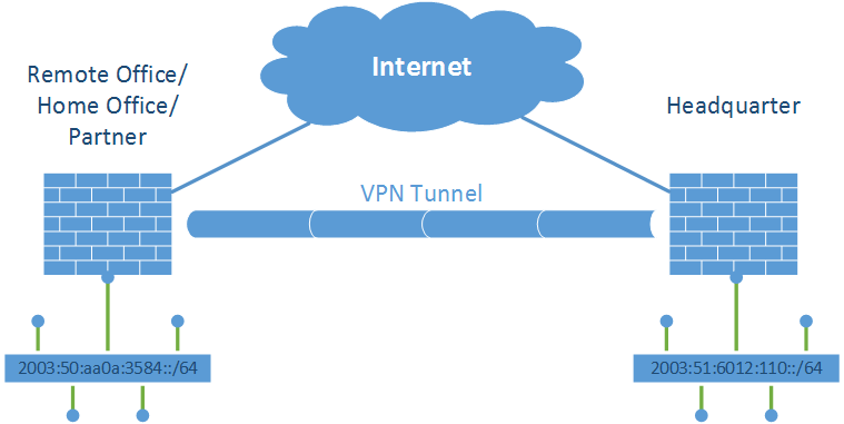
Similar to my test lab for OSPFv2, I am testing OSPFv3 for IPv6 with the following devices: Cisco ASA, Cisco Router, Fortinet FortiGate, Juniper SSG, and Palo Alto. I am showing my lab network diagram and the configuration commands/screenshots for all devices. Furthermore, I am listing some basic troubleshooting commands. In the last section, I provide a Tcpdump/Wireshark capture of an initial OSPFv3 run.

I am not going into deep details of OSPFv3 at all. But this lab should give basic hints for configuring OSPFv3 for all of the listed devices.

Lab

This is my test lab. All devices are directly connected via a layer 2 switch:

OSPFv3 Lab

General Information

  • Everything takes place in area 0.0.0.0 (backbone area)
  • Juniper SSG should be the DR: interface priority set to 100.
  • Palo Alto should be the BDR: interface priority set to 50.
  • Router-ID is always set manually according to my IPv4 sheme: 172.16.1.x, where x = the interface-ID from the IPv6 addresses (from ::1 to ::6).
  • Cost for the interfaces as seen in the figure.
  • Passive-interface on all user/access interfaces.
  • Redistribution of the remote access VPN clients on the Cisco ASA (AnyConnect).
  • No authentication is used .

The following devices are in alphabetic order. Beneath each screenshot is a detailed description of the the configuration that is shown.

During the tests, a single Cisco AnyConnect client was connected and therefore redistributed with a /128 IPv6 address prefix.

Cisco ASA

The Cisco ASA 5505 is running version 9.2(4). Following are the configuration and monitoring screenshots:

Enable OSPFv3. Advanced Section. Add Area 0.0.0.0. Enable OSPFv3 on this interface. No Authentication is used. Redistribution of "Static" for the AnyConnect remote access VPN-Client IPv6 addresses. Monitoring the OSPFv3 neighbors. Router LSAs. Network LSAs. AS External LSAs. Link LSAs. Intra Area Prefix LSAs. Routing table (only OSPF routes are shown). Routing table incl. the static IPv6 route to the currently connected VPN client.

This are the relevant CLI commands for the OSPFv3 config:

interface Vlan130
 ipv6 address 2003:51:6012:130::1/64
 ipv6 address autoconfig
 ipv6 enable
 ipv6 ospf cost 100
 ipv6 ospf 1 area 0
 ipv6 ospf encryption null
!
ipv6 router ospf 1
 router-id 172.16.1.3
 passive-interface insideASA130
 passive-interface insideASA131
 log-adjacency-changes
 redistribute static metric 1000
!

While this CLI commands can be used to show the OPSFv3 runtime values:

fd-wv-fw03# show ipv6 ospf

 Routing Process "ospfv3 1" with ID 172.16.1.3
 Event-log enabled, Maximum number of events: 1000, Mode: cyclic
 It is an autonomous system boundary router
 Redistributing External Routes from,
    static with metric 1000
 Initial SPF schedule delay 5000 msecs
 Minimum hold time between two consecutive SPFs 10000 msecs
 Maximum wait time between two consecutive SPFs 10000 msecs
 Minimum LSA interval 5 secs
 Minimum LSA arrival 1000 msecs
 LSA group pacing timer 240 secs
 Interface flood pacing timer 33 msecs
 Retransmission pacing timer 66 msecs
 Number of external LSA 1. Checksum Sum 0x4dac
 Number of areas in this router is 1. 1 normal 0 stub 0 nssa
 Graceful restart helper support disabled
 Reference bandwidth unit is 100 mbps
    Area BACKBONE(0)
        Number of interfaces in this area is 2
        SPF algorithm executed 11 times
        Number of LSA 19. Checksum Sum 0xa3f76
        Number of DCbitless LSA 6
        Number of indication LSA 0
        Number of DoNotAge LSA 0
        Flood list length 0

fd-wv-fw03#
fd-wv-fw03#
fd-wv-fw03# show ipv6 ospf neighbor


Neighbor ID     Pri   State           Dead Time   Interface ID    Interface
     172.16.1.1 100   2WAY/DROTHER    0:00:36                880 outside
     172.16.1.2 50    FULL/DR         0:00:34                 16 outside
     172.16.1.5 1     FULL/BDR        0:00:30                  3 outside
     172.16.1.6 1     2WAY/DROTHER    0:00:31                  6 outside
fd-wv-fw03#
fd-wv-fw03#
fd-wv-fw03# show ipv6 ospf database


            OSPFv3 Router with ID (172.16.1.3) (Process ID 1)

                Router Link States (Area 0)

ADV Router       Age         Seq#        Fragment ID  Link count  Bits
      172.16.1.1   1608      0x80000122             1           1 None
      172.16.1.2    636      0x80000124             0           1 E
      172.16.1.3   1461      0x80000102             0           1 E
      172.16.1.5     74      0x80000102             0           1 None
      172.16.1.6   1371      0x80000122             0           1 None

                Net Link States (Area 0)

ADV Router       Age         Seq#        Link ID    Rtr count
      172.16.1.2    634      0x80000122          16 5

                Link (Type-8) Link States (Area 0)

ADV Router       Age         Seq#        Link ID    Interface
      172.16.1.3    430      0x80000008          15 insideASA130
      172.16.1.1   1653      0x8000011d         880 outside
      172.16.1.2   1310      0x8000011e          16 outside
      172.16.1.3    945      0x80000101          14 outside
      172.16.1.5     74      0x80000101           3 outside
      172.16.1.6   1441      0x8000011d           6 outside

                Intra Area Prefix Link States (Area 0)

ADV Router       Age         Seq#        Link ID    Ref-lstype  Ref-LSID
      172.16.1.1   1648      0x80000242           1 0x2001      0
      172.16.1.2    637      0x80000124           1 0x2001      0
      172.16.1.2    629      0x80000129      458752 0x2002      16
      172.16.1.2    637      0x8000011f      589824 0x2002      257
      172.16.1.3    946      0x80000101           0 0x2001      0
      172.16.1.5   1327      0x80000006           0 0x2001      0
      172.16.1.6   1370      0x80000120           2 0x2001      0

                Type-5 AS External Link States

ADV Router       Age         Seq#       Prefix
      172.16.1.3    606      0x80000001  2003:51:6012:133:feed:cafe:0:10/128
fd-wv-fw03#
fd-wv-fw03#
fd-wv-fw03# show ipv6 ospf database self-originate


            OSPFv3 Router with ID (172.16.1.3) (Process ID 1)

                Router Link States (Area 0)

ADV Router       Age         Seq#        Fragment ID  Link count  Bits
      172.16.1.3   1495      0x80000102             0           1 E

                Link (Type-8) Link States (Area 0)

ADV Router       Age         Seq#        Link ID    Interface
      172.16.1.3    464      0x80000008          15 insideASA130
      172.16.1.3    979      0x80000101          14 outside

                Intra Area Prefix Link States (Area 0)

ADV Router       Age         Seq#        Link ID    Ref-lstype  Ref-LSID
      172.16.1.3    979      0x80000101           0 0x2001      0

                Type-5 AS External Link States

ADV Router       Age         Seq#       Prefix
      172.16.1.3    639      0x80000001  2003:51:6012:133:feed:cafe:0:10/128
fd-wv-fw03#
fd-wv-fw03#


Cisco Router

I am running a Cisco 2811 router with version 15.1(4)M9. The configuration commands are the following: (Just for fun I set the OSPF process to “17”.)

interface FastEthernet0/0
 ipv6 address 2003:51:6012:101::5/64
 ipv6 enable
 ipv6 nd ra suppress
 ipv6 ospf 17 area 0.0.0.0
!
interface FastEthernet0/1
 ipv6 address 2003:61:6012:102::1/64
 ipv6 enable
 ipv6 ospf 17 area 0.0.0.0
!
ipv6 router ospf 17
 router-id 172.16.1.5
 auto-cost reference-bandwidth 10000
 passive-interface default
 no passive-interface FastEthernet0/0

And the show commands:

fd-wv-ro03#show ipv6 ospf
 Routing Process "ospfv3 17" with ID 172.16.1.5
 Event-log enabled, Maximum number of events: 1000, Mode: cyclic
 Initial SPF schedule delay 5000 msecs
 Minimum hold time between two consecutive SPFs 10000 msecs
 Maximum wait time between two consecutive SPFs 10000 msecs
 Minimum LSA interval 5 secs
 Minimum LSA arrival 1000 msecs
 LSA group pacing timer 240 secs
 Interface flood pacing timer 33 msecs
 Retransmission pacing timer 66 msecs
 Number of external LSA 1. Checksum Sum 0x004DAC
 Number of areas in this router is 1. 1 normal 0 stub 0 nssa
 Graceful restart helper support enabled
 Reference bandwidth unit is 10000 mbps
    Area BACKBONE(0.0.0.0)
        Number of interfaces in this area is 2
        SPF algorithm executed 23 times
        Number of LSA 19. Checksum Sum 0x098B75
        Number of DCbitless LSA 6
        Number of indication LSA 0
        Number of DoNotAge LSA 0
        Flood list length 0

fd-wv-ro03#
fd-wv-ro03#
fd-wv-ro03#show ipv6 ospf neighbor

Neighbor ID     Pri   State           Dead Time   Interface ID    Interface
172.16.1.1      100   FULL/DROTHER    00:00:35    880             FastEthernet0/0
172.16.1.2       50   FULL/DR         00:00:32    16              FastEthernet0/0
172.16.1.3        1   FULL/DROTHER    00:00:38    14              FastEthernet0/0
172.16.1.6        1   FULL/DROTHER    00:00:30    6               FastEthernet0/0
fd-wv-ro03#
fd-wv-ro03#
fd-wv-ro03#show ipv6 ospf database

            OSPFv3 Router with ID (172.16.1.5) (Process ID 17)

                Router Link States (Area 0.0.0.0)

ADV Router       Age         Seq#        Fragment ID  Link count  Bits
 172.16.1.1      622         0x80000123  1            1           None
 172.16.1.2      1455        0x80000124  0            1           E
 172.16.1.3      243         0x80000103  0            1           E
 172.16.1.5      892         0x80000102  0            1           None
 172.16.1.6      389         0x80000123  0            1           None

                Net Link States (Area 0.0.0.0)

ADV Router       Age         Seq#        Link ID    Rtr count
 172.16.1.2      1453        0x80000122  16         5

                Link (Type-8) Link States (Area 0.0.0.0)

ADV Router       Age         Seq#        Link ID    Interface
 172.16.1.5      131         0x80000007  4          Fa0/1
 172.16.1.1      667         0x8000011E  880        Fa0/0
 172.16.1.2      330         0x8000011F  16         Fa0/0
 172.16.1.3      1766        0x80000101  14         Fa0/0
 172.16.1.5      892         0x80000101  3          Fa0/0
 172.16.1.6      459         0x8000011E  6          Fa0/0

                Intra Area Prefix Link States (Area 0.0.0.0)

ADV Router       Age         Seq#        Link ID    Ref-lstype  Ref-LSID
 172.16.1.1      662         0x80000244  1          0x2001      0
 172.16.1.2      1455        0x80000124  1          0x2001      0
 172.16.1.2      1448        0x80000129  458752     0x2002      16
 172.16.1.2      1455        0x8000011F  589824     0x2002      257
 172.16.1.3      1766        0x80000101  0          0x2001      0
 172.16.1.5      131         0x80000007  0          0x2001      0
 172.16.1.6      388         0x80000121  2          0x2001      0

                Type-5 AS External Link States

ADV Router       Age         Seq#       Prefix
 172.16.1.3      1426        0x80000001  2003:51:6012:133:FEED:CAFE:0:10/128
fd-wv-ro03#
fd-wv-ro03#
fd-wv-ro03#show ipv6 ospf database self-originate

            OSPFv3 Router with ID (172.16.1.5) (Process ID 17)

                Router Link States (Area 0.0.0.0)

ADV Router       Age         Seq#        Fragment ID  Link count  Bits
 172.16.1.5      898         0x80000102  0            1           None

                Link (Type-8) Link States (Area 0.0.0.0)

ADV Router       Age         Seq#        Link ID    Interface
 172.16.1.5      137         0x80000007  4          Fa0/1
 172.16.1.5      898         0x80000101  3          Fa0/0

                Intra Area Prefix Link States (Area 0.0.0.0)

ADV Router       Age         Seq#        Link ID    Ref-lstype  Ref-LSID
 172.16.1.5      137         0x80000007  0          0x2001      0
fd-wv-ro03#
fd-wv-ro03#
fd-wv-ro03#show ipv6 route
IPv6 Routing Table - default - 15 entries
Codes: C - Connected, L - Local, S - Static, U - Per-user Static route
       B - BGP, HA - Home Agent, MR - Mobile Router, R - RIP
       I1 - ISIS L1, I2 - ISIS L2, IA - ISIS interarea, IS - ISIS summary
       D - EIGRP, EX - EIGRP external, NM - NEMO, ND - Neighbor Discovery
       l - LISP
       O - OSPF Intra, OI - OSPF Inter, OE1 - OSPF ext 1, OE2 - OSPF ext 2
       ON1 - OSPF NSSA ext 1, ON2 - OSPF NSSA ext 2
S   ::/0 [1/0]
     via 2003:51:6012:101::1
C   2003:51:6012:101::/64 [0/0]
     via FastEthernet0/0, directly connected
L   2003:51:6012:101::5/128 [0/0]
     via FastEthernet0/0, receive
O   2003:51:6012:110::/64 [110/200]
     via FE80::219:E2FF:FEA1:F98A, FastEthernet0/0
O   2003:51:6012:120::/64 [110/110]
     via FE80::B60C:25FF:FE05:8E10, FastEthernet0/0
O   2003:51:6012:121::/64 [110/110]
     via FE80::B60C:25FF:FE05:8E10, FastEthernet0/0
O   2003:51:6012:123::/64 [110/110]
     via FE80::B60C:25FF:FE05:8E10, FastEthernet0/0
O   2003:51:6012:124::/64 [110/110]
     via FE80::B60C:25FF:FE05:8E10, FastEthernet0/0
O   2003:51:6012:125::/64 [110/110]
     via FE80::B60C:25FF:FE05:8E10, FastEthernet0/0
O   2003:51:6012:130::/64 [110/200]
     via FE80::2A94:FFF:FEA8:772D, FastEthernet0/0
OE2 2003:51:6012:133:FEED:CAFE:0:10/128 [110/1000]
     via FE80::2A94:FFF:FEA8:772D, FastEthernet0/0
O   2003:51:6012:160::/64 [110/200]
     via FE80::A5B:EFF:FE3C:115D, FastEthernet0/0
C   2003:61:6012:102::/64 [0/0]
     via FastEthernet0/1, directly connected
L   2003:61:6012:102::1/128 [0/0]
     via FastEthernet0/1, receive
L   FF00::/8 [0/0]
     via Null0, receive
fd-wv-ro03#
fd-wv-ro03#


Fortinet FortiGate

Unfortunately the FortiGate has no possibility to configure anything of OSPFv3 via the GUI. Everything must be done via the CLI. (And this is called a “Next-Generation Firewall”???)

These are the configuration commands for my lab:

config router ospf6
    set auto-cost-ref-bandwidth 10000
    set router-id 172.16.1.6
        config area
            edit 0.0.0.0
            next
        end
        config ospf6-interface
            edit "wan1"
                set interface "wan1"
            next
            edit "fg-trust"
                set interface "fg-trust"
            next
        end
    set passive-interface "fg-trust"

And the following shows the get commands:

fd-wv-fw04 # get router info6 ospf status
 Routing Process "OSPFv3 (*null*)" with ID 172.16.1.6
 Process uptime is 50 days 22 hours 5 minutes
 SPF schedule delay 5 secs, Hold time between SPFs 10 secs
 Minimum LSA interval 5 secs, Minimum LSA arrival 1 secs
 Number of incomming current DD exchange neighbors 0/5
 Number of outgoing current DD exchange neighbors 0/5
 Number of external LSA 1. Checksum Sum 0x4BAD
 Number of AS-Scoped Unknown LSA 0
 Number of LSA originated 23
 Number of LSA received 37398
 Number of areas in this router is 2
    Area BACKBONE(0)
        Number of interfaces in this area is 2(2)
        SPF algorithm executed 15 times
        Number of LSA 13.  Checksum Sum 0x5C289
        Number of Unknown LSA 0
    Area 0.0.0.51 (Inactive)
        Number of interfaces in this area is 0(0)
        SPF algorithm executed 33 times
        Number of LSA 0.  Checksum Sum 0x0000
        Number of Unknown LSA 0


fd-wv-fw04 #
fd-wv-fw04 #
fd-wv-fw04 # get router info6 ospf neighbor
OSPFv3 Process (*null*)
Neighbor ID     Pri   State           Dead Time   Interface  Instance ID
172.16.1.1      100   2-Way/DROther   00:00:36    wan1       0
172.16.1.2       50   Full/DR         00:00:31    wan1       0
172.16.1.3        1   2-Way/DROther   00:00:32    wan1       0
172.16.1.5        1   Full/Backup     00:00:37    wan1       0


fd-wv-fw04 #
fd-wv-fw04 #
fd-wv-fw04 # get router info6 ospf database

            OSPFv3 Router with ID (172.16.1.6) (Process *null*)

                Link-LSA (Interface wan1)

Link State ID   ADV Router      Age  Seq#       CkSum  Prefix
0.0.3.112       172.16.1.1      1496 0x8000011e 0x6247      1
0.0.0.16        172.16.1.2      1158 0x8000011f 0x4293      1
0.0.0.14        172.16.1.3       578 0x80000102 0xf084      1
0.0.0.3         172.16.1.5      1722 0x80000101 0xf2b9      1
0.0.0.6         172.16.1.6      1287 0x8000011e 0xf486      1

                Link-LSA (Interface fg-trust)

Link State ID   ADV Router      Age  Seq#       CkSum  Prefix
0.0.0.63        172.16.1.6      1261 0x8000011e 0xca19      1

                Router-LSA (Area 0.0.0.0)

Link State ID   ADV Router      Age  Seq#       CkSum    Link
0.0.0.1         172.16.1.1      1451 0x80000123 0x197c      1
0.0.0.0         172.16.1.2       484 0x80000125 0x2b24      1
0.0.0.0         172.16.1.3      1073 0x80000103 0x9562      1
0.0.0.0         172.16.1.5      1722 0x80000102 0xea19      1
0.0.0.0         172.16.1.6      1217 0x80000123 0x84d4      1

                Network-LSA (Area 0.0.0.0)

Link State ID   ADV Router      Age  Seq#       CkSum
0.0.0.16        172.16.1.2       482 0x80000123 0xb390

                Intra-Area-Prefix-LSA (Area 0.0.0.0)

Link State ID   ADV Router      Age  Seq#       CkSum  Prefix  Reference
0.0.0.1         172.16.1.1      1491 0x80000244 0x6d9e      2  Router-LSA
0.0.0.1         172.16.1.2       484 0x80000125 0x265e      5  Router-LSA
0.7.0.0         172.16.1.2       477 0x8000012a 0xb764      1  Network-LSA
0.9.0.0         172.16.1.2       484 0x80000120 0x4fc3      1  Network-LSA
0.0.0.0         172.16.1.3       578 0x80000102 0x972f      1  Router-LSA
0.0.0.0         172.16.1.5       961 0x80000007 0x518b      1  Router-LSA
0.0.0.2         172.16.1.6      1216 0x80000121 0x422d      1  Router-LSA

                AS-external-LSA

Link State ID   ADV Router      Age  Seq#       CkSum
0.0.0.0         172.16.1.3       321 0x80000002 0x4bad E2


fd-wv-fw04 #
fd-wv-fw04 #
fd-wv-fw04 # get router info6 ospf route
OSPFv3 Process (*null*)
Codes: C - connected, D - Discard, O - OSPF, IA - OSPF inter area
       N1 - OSPF NSSA external type 1, N2 - OSPF NSSA external type 2
       E1 - OSPF external type 1, E2 - OSPF external type 2

   Destination                                   Metric
     Next-hop
C  2003:51:6012:101::/64                             10
     directly connected, wan1, Area 0.0.0.0
O  2003:51:6012:110::/64                            110
     via fe80::219:e2ff:fea1:f98a, wan1, Area 0.0.0.0
O  2003:51:6012:120::/64                             20
     via fe80::b60c:25ff:fe05:8e10, wan1, Area 0.0.0.0
O  2003:51:6012:121::/64                             20
     via fe80::b60c:25ff:fe05:8e10, wan1, Area 0.0.0.0
O  2003:51:6012:123::/64                             20
     via fe80::b60c:25ff:fe05:8e10, wan1, Area 0.0.0.0
O  2003:51:6012:124::/64                             20
     via fe80::b60c:25ff:fe05:8e10, wan1, Area 0.0.0.0
O  2003:51:6012:125::/64                             20
     via fe80::b60c:25ff:fe05:8e10, wan1, Area 0.0.0.0
O  2003:51:6012:130::/64                            110
     via fe80::2a94:fff:fea8:772d, wan1, Area 0.0.0.0
E2 2003:51:6012:133:feed:cafe:0:10/128          10/1000
     via fe80::2a94:fff:fea8:772d, wan1
C  2003:51:6012:160::/64                            100
     directly connected, fg-trust, Area 0.0.0.0
O  2003:61:6012:102::/64                            110
     via fe80::21a:6cff:fea1:2b98, wan1, Area 0.0.0.0

fd-wv-fw04 #
fd-wv-fw04 #


Furthermore, the GUI can at least show the routing table:

FortiGate Routing Monitor.


Juniper ScreenOS

My SSG 5 runs at version 6.3.0r19. Unlike OSPF for IPv4, in which the “enable” checkmark for each interface is inside the interface configuration section, OSPFv3 is completely configured inside the virtual routers menu:

Set the Router ID. This must be done BEFORE any routing protocol is activated. Create/Edit the OSPFv3 instance. Enabling OSPFv3. Add the area. And add the interfaces. OSPFv3 MUST be enabled on each interface, too. Enabling of OSPFv3 and setting all other values such as cost, priority, or passive mode. Screenshot of the routing table with various "O" protocol entries.

The config commands via the CLI are the following:

set vrouter trust-vr protocol ospfv3 enable
set vrouter trust-vr protocol ospfv3 area 0.0.0.0
set interface ethernet0/5.10 protocol ospfv3 area 0.0.0.0
set interface ethernet0/5.10 protocol ospfv3 passive
set interface ethernet0/5.10 protocol ospfv3 enable
set interface ethernet0/5.10 protocol ospfv3 cost 100
set interface ethernet0/6 protocol ospfv3 area 0.0.0.0
set interface ethernet0/6 protocol ospfv3 enable
set interface ethernet0/6 protocol ospfv3 priority 100
set interface ethernet0/6 protocol ospfv3 cost 100

And the get commands for displaying the runtime values are this:

fd-wv-fw01-> get vrouter trust-vr protocol ospfv3
VR: trust-vr RouterId: 172.16.1.1
----------------------------------
Status:                                 enabled
State:                                  internal router
Number of areas:                        1
Number of LSA(s):                       20
Number of AS-flooding-scope LSA(s):     1
Area 0.0.0.0
        Total number of interfaces is 2, Active number of interfaces is 2
        Intra-SPF algorithm executed 25 times
        Last Intra-SPF executed before 03:30:25
        Number of LSA(s) is 19

Inter-SPF algorithm executed: 27 times
Last Inter-SPF executed before 01:01:30
Extern-SPF algorithm executed: 28 times
Last Extern-SPF executed before 01:01:30
fd-wv-fw01->
fd-wv-fw01->
fd-wv-fw01-> get vrouter trust-vr protocol ospfv3 neighbor
VR: trust-vr RouterId: 172.16.1.1
----------------------------------
                Neighbor(s) on interface ethernet0/5.10 (Area 0.0.0.0)

                Neighbor(s) on interface ethernet0/6 (Area 0.0.0.0)
RouterId        Nbr-saw-DR      Nbr-saw-BDR     Nbr-If-Id  Opt      Pri State   (Down, Up)
------------------------------------------------------------------------------
172.16.1.3      172.16.1.2      172.16.1.5      0x0000000e --V6|E|R 1   2WAY    (+2    -0)
172.16.1.6      172.16.1.2      172.16.1.5      0x00000006 --V6|E|R 1   2WAY    (+2    -0)
172.16.1.2      172.16.1.2      172.16.1.5      0x00000010 --V6|E|R 50  FULL    (+6    -0)
172.16.1.5      172.16.1.2      172.16.1.5      0x00000003 --V6|E|R 1   FULL    (+6    -0)

fd-wv-fw01->
fd-wv-fw01->
fd-wv-fw01-> get vrouter trust-vr protocol ospfv3 database
VR: trust-vr RouterId: 172.16.1.1
----------------------------------


As-External-LSA
--------------------------------------------------------------------------------
Link-State-Id     Adv-Router-Id      Age      Sequence#    CheckSum
--------------------------------------------------------------------------------
0x00000000        172.16.1.3         1786     0x80000002   0x4bad


Router-LSA for area 0.0.0.0
--------------------------------------------------------------------------------
Link-State-Id     Adv-Router-Id      Age      Sequence#    CheckSum
--------------------------------------------------------------------------------
0x00000000        172.16.1.5         1169     0x80000103   0xe81a
0x00000000        172.16.1.6         884      0x80000124   0x82d5
0x00000001        172.16.1.1         1111     0x80000124   0x177d
0x00000000        172.16.1.3         516      0x80000104   0x9363
0x00000000        172.16.1.2         149      0x80000126   0x2925


Network-LSA for area 0.0.0.0
--------------------------------------------------------------------------------
Link-State-Id     Adv-Router-Id      Age      Sequence#    CheckSum
--------------------------------------------------------------------------------
0x00000010        172.16.1.2         147      0x80000124   0xb191


Intra-Area-Prefix-LSA for area 0.0.0.0
--------------------------------------------------------------------------------
Link-State-Id     Adv-Router-Id      Age      Sequence#    CheckSum
--------------------------------------------------------------------------------
0x00000000        172.16.1.5         417      0x80000008   0x4f8c
0x00000002        172.16.1.6         884      0x80000122   0x402e
0x00000001        172.16.1.1         1152     0x80000246   0x69a0
0x00000000        172.16.1.3         13       0x80000103   0x9530
0x00000001        172.16.1.2         150      0x80000126   0x245f
0x00070000        172.16.1.2         143      0x8000012b   0xb565
0x00090000        172.16.1.2         150      0x80000121   0x4dc4


Link-LSA for link ethernet0/5.10, area 0.0.0.0
--------------------------------------------------------------------------------
Link-State-Id     Adv-Router-Id      Age      Sequence#    CheckSum
--------------------------------------------------------------------------------
0x00000368        172.16.1.1         1157     0x8000011f   0xac59


Link-LSA for link ethernet0/6, area 0.0.0.0
--------------------------------------------------------------------------------
Link-State-Id     Adv-Router-Id      Age      Sequence#    CheckSum
--------------------------------------------------------------------------------
0x00000003        172.16.1.5         1171     0x80000102   0xf0ba
0x00000006        172.16.1.6         956      0x8000011f   0xf287
0x00000370        172.16.1.1         1158     0x8000011f   0x6048
0x0000000e        172.16.1.3         14       0x80000103   0xee85
0x00000010        172.16.1.2         826      0x80000120   0x4094

-----------------------
 printed 20 LSA(s).
fd-wv-fw01->
fd-wv-fw01->
fd-wv-fw01-> get vrouter trust-vr protocol ospfv3 database self-originate
VR: trust-vr RouterId: 172.16.1.1
----------------------------------


Router-LSA for area 0.0.0.0
--------------------------------------------------------------------------------
Link-State-Id     Adv-Router-Id      Age      Sequence#    CheckSum
--------------------------------------------------------------------------------
0x00000001        172.16.1.1         1129     0x80000124   0x177d


Intra-Area-Prefix-LSA for area 0.0.0.0
--------------------------------------------------------------------------------
Link-State-Id     Adv-Router-Id      Age      Sequence#    CheckSum
--------------------------------------------------------------------------------
0x00000001        172.16.1.1         1169     0x80000246   0x69a0


Link-LSA for link ethernet0/5.10, area 0.0.0.0
--------------------------------------------------------------------------------
Link-State-Id     Adv-Router-Id      Age      Sequence#    CheckSum
--------------------------------------------------------------------------------
0x00000368        172.16.1.1         1174     0x8000011f   0xac59


Link-LSA for link ethernet0/6, area 0.0.0.0
--------------------------------------------------------------------------------
Link-State-Id     Adv-Router-Id      Age      Sequence#    CheckSum
--------------------------------------------------------------------------------
0x00000370        172.16.1.1         1175     0x8000011f   0x6048

-----------------------
 printed 4 LSA(s).
fd-wv-fw01->
fd-wv-fw01->
fd-wv-fw01-> get vrouter trust-vr route protocol ospfv3
H: Host C: Connected S: Static A: Auto-Exported
I: Imported R: RIP/RIPng P: Permanent D: Auto-Discovered
N: NHRP
iB: IBGP eB: EBGP O: OSPF/OSPFv3 E1: OSPF external type 1
E2: OSPF/OSPFv3 external type 2 trailing B: backup route

Total 19/max entries

         ID                                   IP-Prefix       Interface
                                                Gateway   P Pref    Mtr     Vsys
--------------------------------------------------------------------------------------
         56                       2003:51:6012:101::/64          eth0/6
                                                     ::   O   60    100     Root
*        67         2003:51:6012:133:feed:cafe:0:10/128          eth0/6
                               fe80::2a94:fff:fea8:772d  E2  200   1000     Root
         54                       2003:51:6012:110::/64       eth0/5.10
                                                     ::   O   60    100     Root
*        57                       2003:51:6012:121::/64          eth0/6
                              fe80::b60c:25ff:fe05:8e10   O   60    110     Root
*        58                       2003:51:6012:120::/64          eth0/6
                              fe80::b60c:25ff:fe05:8e10   O   60    110     Root
*        59                       2003:51:6012:123::/64          eth0/6
                              fe80::b60c:25ff:fe05:8e10   O   60    110     Root
*        60                       2003:51:6012:125::/64          eth0/6
                              fe80::b60c:25ff:fe05:8e10   O   60    110     Root
*        61                       2003:51:6012:124::/64          eth0/6
                              fe80::b60c:25ff:fe05:8e10   O   60    110     Root
*        64                       2003:51:6012:130::/64          eth0/6
                               fe80::2a94:fff:fea8:772d   O   60    200     Root
*        66                       2003:61:6012:102::/64          eth0/6
                               fe80::21a:6cff:fea1:2b98   O   60    200     Root
*        63                       2003:51:6012:160::/64          eth0/6
                                fe80::a5b:eff:fe3c:115d   O   60    200     Root

Total number of ospfv3 routes: 11
fd-wv-fw01->
fd-wv-fw01->


Palo Alto

Finally, this is the Palo Alto guide. I am using a PA-200 with version 7.0.2. To my mind, this is the best OSPFv3 GUI from all firewalls in my lab. Here we go:

Open the virtual router and enable OSPFv3 with a Router ID. Then, "Add" an area. Area General tab. Add the interfaces. And enable OSPFv3 for each interface. Futhermore, set the values such as metric, priority, and passive mode. Don't forget to allow OSPF on the security policy! Traffic log which shows several OSPFv3 sessions. The "More Runtime Stats" button on the virtual router displays the routing table, for example. As well as the OSPFv3 summary. And OSPFv3 neighbors.

To show some runtime stats on the CLI, use this show commands:

weberjoh@fd-wv-fw02> show routing protocol ospfv3 summary

Router ID 172.16.1.2, instance 0 in virtual router default
  OSPFv3 is up, oper status active
  ABR: no, ASBR: yes, Allow transit traffic: yes
  reject-default-route: yes , redist-default-route: n/a
  originated LSA count: 3497, received LSA count: 6676
  num AS-scoped LSA: 0, AS-external LSA count: 1
  num update pending: 0, num update merged: 1
  SPF calc delay: 5.00, min lsa interval : 5.00
  external refresh interval: 1800

weberjoh@fd-wv-fw02>
weberjoh@fd-wv-fw02> show routing protocol ospfv3 neighbor

Neighbor ID 172.16.1.1, in virtual router default
  Neighbor Link-local addr fe80:0:0:0:219:e2ff:fea1:f98a,Neighbor If ID 880
  Through local Interface ethernet1/1, local IF ID 16
  Area 0.0.0.0, instance ID 0, status up
  priority 100, state full, event count 10
  Options 0x13, V6(1),E(1),MC(0),N(0),R(1),DC(0)
  Retransmission queue length 0, Waiting on 0 LSA request
  Dead time is 38 sec
  Graceful restart helper status: not helping, time remaining: 0
  Graceful restart helper exit reason: none
Neighbor ID 172.16.1.3, in virtual router default
  Neighbor Link-local addr fe80:0:0:0:2a94:fff:fea8:772d,Neighbor If ID 14
  Through local Interface ethernet1/1, local IF ID 16
  Area 0.0.0.0, instance ID 0, status up
  priority 1, state full, event count 6
  Options 0x13, V6(1),E(1),MC(0),N(0),R(1),DC(0)
  Retransmission queue length 0, Waiting on 0 LSA request
  Dead time is 31 sec
  Graceful restart helper status: not helping, time remaining: 0
  Graceful restart helper exit reason: none
Neighbor ID 172.16.1.5, in virtual router default
  Neighbor Link-local addr fe80:0:0:0:21a:6cff:fea1:2b98,Neighbor If ID 3
  Through local Interface ethernet1/1, local IF ID 16
  Area 0.0.0.0, instance ID 0, status up
  priority 1, state full, event count 6
  Options 0x13, V6(1),E(1),MC(0),N(0),R(1),DC(0)
  Retransmission queue length 0, Waiting on 0 LSA request
  Dead time is 37 sec
  Graceful restart helper status: not helping, time remaining: 0
  Graceful restart helper exit reason: none
Neighbor ID 172.16.1.6, in virtual router default
  Neighbor Link-local addr fe80:0:0:0:a5b:eff:fe3c:115d,Neighbor If ID 6
  Through local Interface ethernet1/1, local IF ID 16
  Area 0.0.0.0, instance ID 0, status up
  priority 1, state full, event count 6
  Options 0x13, V6(1),E(1),MC(0),N(0),R(1),DC(0)
  Retransmission queue length 0, Waiting on 0 LSA request
  Dead time is 29 sec
  Graceful restart helper status: not helping, time remaining: 0
  Graceful restart helper exit reason: none

weberjoh@fd-wv-fw02>
weberjoh@fd-wv-fw02> show routing protocol ospfv3 dumplsdb

** OSPF AS-Scope link state database
 VIRTUAL ROUTER: default (id 1)
 VR Type       Adv Router ID   LS id           Seq ID     Cksum  Age   Size
  1 External   172.16.1.3      0.0.0.1         0x80000003 0x3FB7 638   44
     Flags [External Type 2], metric 1000
        2003:51:6012:133:feed:cafe:0:10/128
** OSPF Area Scope link state database
 VIRTUAL ROUTER: default (id 1)
 VR Type       Adv Router ID   LS id           Seq ID     Cksum  Age   Size
  1 Router     172.16.1.1      0.0.0.1         0x8000017B 0x68D4 1698  40
      Options [V6, External, Router], RLA-Flags [none]
      Neighbor Network-ID 172.16.1.2
      Neighbor Interface-ID 0.0.0.16, Interface ID 0.0.3.112
      type 2, metric 100
  1 Router     172.16.1.2      0.0.0.0         0x8000017D 0x7A7C 1131  40
      Options [V6, External, Router], RLA-Flags [External]
      Neighbor Network-ID 172.16.1.2
      Neighbor Interface-ID 0.0.0.16, Interface ID 0.0.0.16
      type 2, metric 10
  1 Router     172.16.1.3      0.0.0.0         0x80000152 0xF6B1 884   40
      Options [V6, External, Router, Demand Circuit], RLA-Flags [External]
      Neighbor Network-ID 172.16.1.2
      Neighbor Interface-ID 0.0.0.16, Interface ID 0.0.0.14
      type 2, metric 100
  1 Router     172.16.1.5      0.0.0.0         0x80000152 0x4A69 296   40
      Options [V6, External, Router, Demand Circuit], RLA-Flags [none]
      Neighbor Network-ID 172.16.1.2
      Neighbor Interface-ID 0.0.0.16, Interface ID 0.0.0.3
      type 2, metric 100
  1 Router     172.16.1.6      0.0.0.0         0x8000017C 0xD12E 68    40
      Options [V6, External, Router], RLA-Flags [none]
      Neighbor Network-ID 172.16.1.2
      Neighbor Interface-ID 0.0.0.16, Interface ID 0.0.0.6
      type 2, metric 10
  1 Network    172.16.1.2      0.0.0.16        0x8000017B 0x3E8  1129  44
      Options [V6, External, Router, Demand Circuit]
      Connected Routers:
        172.16.1.1
        172.16.1.3
        172.16.1.5
        172.16.1.6
        172.16.1.2
  1 IntraArPfx 172.16.1.1      0.0.0.1         0x800002F4 0xC4F  1737  56
      Prefixes 2:
        2003:51:6012:110:0:0:0:0/64, metric 100
        2003:51:6012:101:0:0:0:0/64, metric 100
  1 IntraArPfx 172.16.1.2      0.0.0.1         0x8000017D 0x75B6 1131  92
      Prefixes 5:
        2003:51:6012:123:0:0:0:0/64, metric 10
        2003:51:6012:120:0:0:0:0/64, metric 10
        2003:51:6012:125:0:0:0:0/64, metric 10
        2003:51:6012:121:0:0:0:0/64, metric 10
        2003:51:6012:124:0:0:0:0/64, metric 10
  1 IntraArPfx 172.16.1.2      0.7.0.0         0x80000182 0x7BC  1124  44
      Prefixes 1:
        2003:51:6012:101:0:0:0:0/64, metric 0
  1 IntraArPfx 172.16.1.2      0.9.0.0         0x80000178 0x9E1C 1131  44
      Prefixes 1:
        2003:51:6012:120:0:0:0:0/64, metric 0
  1 IntraArPfx 172.16.1.3      0.0.0.0         0x80000151 0xF87E 884   44
      Prefixes 1:
        2003:51:6012:130:0:0:0:0/64, metric 100
  1 IntraArPfx 172.16.1.5      0.0.0.0         0x80000056 0xB2DA 1272  44
      Prefixes 1:
        2003:61:6012:102:0:0:0:0/64, metric 100
  1 IntraArPfx 172.16.1.6      0.0.0.2         0x8000017A 0x8F86 67    44
      Prefixes 1:
        2003:51:6012:160:0:0:0:0/64, metric 100
** OSPF Link Scope link state database
 VIRTUAL ROUTER: default (id 1)
 VR Type       Adv Router ID   LS id           Seq ID     Cksum  Age   Size
  1 Link       172.16.1.1      0.0.3.112       0x80000176 0xB19F 1742  56
      Options [V6, External, Router]
      Priority 100, Link-local address fe80:0:0:0:219:e2ff:fea1:f98a,
      Prefixes 1:
        2003:51:6012:101:0:0:0:0/64
  1 Link       172.16.1.2      0.0.0.16        0x80000178 0x8FEC 5     56
      Options [V6, External, Router]
      Priority 50, Link-local address fe80:0:0:0:b60c:25ff:fe05:8e10,
      Prefixes 1:
        2003:51:6012:101:0:0:0:0/64
  1 Link       172.16.1.3      0.0.0.14        0x80000151 0x52D3 884   56
      Options [V6, External, Router, Demand Circuit]
      Priority 1, Link-local address fe80:0:0:0:2a94:fff:fea8:772d,
      Prefixes 1:
        2003:51:6012:101:0:0:0:0/64
  1 Link       172.16.1.5      0.0.0.3         0x80000151 0x520A 296   56
      Options [V6, External, Router, Demand Circuit]
      Priority 1, Link-local address fe80:0:0:0:21a:6cff:fea1:2b98,
      Prefixes 1:
        2003:51:6012:101:0:0:0:0/64
  1 Link       172.16.1.6      0.0.0.6         0x80000177 0x42DF 137   56
      Options [V6, External, Router]
      Priority 1, Link-local address fe80:0:0:0:a5b:eff:fe3c:115d,
      Prefixes 1:
        2003:51:6012:101:0:0:0:0/64
  1 Link       172.16.1.2      0.0.1.1         0x80000178 0x92A3 5     56
      Options [V6, External, Router]
      Priority 100, Link-local address fe80:0:0:0:b60c:25ff:fe05:8e13,
      Prefixes 1:
        2003:51:6012:120:0:0:0:0/64
weberjoh@fd-wv-fw02>
weberjoh@fd-wv-fw02> show routing route type ospf

flags: A:active, ?:loose, C:connect, H:host, S:static, ~:internal, R:rip, O:ospf, B:bgp,
       Oi:ospf intra-area, Oo:ospf inter-area, O1:ospf ext-type-1, O2:ospf ext-type-2, E:ecmp


VIRTUAL ROUTER: default (id 1)
  ==========
destination                                 nexthop                                 metric flags      age   interface          next-AS
[IPv4 routes omitted]
2003:51:6012:101::/64                       ::                                      10       Oi       675410 ethernet1/1
2003:51:6012:110::/64                       fe80::219:e2ff:fea1:f98a                110    A Oi       674960 ethernet1/1
2003:51:6012:120::/64                       ::                                      10       Oi       945349 ethernet1/4.120
2003:51:6012:121::/64                       ::                                      10       Oi       945349 ethernet1/4.121
2003:51:6012:123::/64                       ::                                      10       Oi       945349 ethernet1/3
2003:51:6012:124::/64                       ::                                      10       Oi       945349 ethernet1/4.124
2003:51:6012:125::/64                       ::                                      10       Oi       945349 ethernet1/4.125
2003:51:6012:130::/64                       fe80::2a94:fff:fea8:772d                110    A Oi       672653 ethernet1/1
2003:51:6012:133:feed:cafe:0:10/128         fe80::2a94:fff:fea8:772d                1000   A O2       4598  ethernet1/1
2003:51:6012:160::/64                       fe80::a5b:eff:fe3c:115d                 110    A Oi       673436 ethernet1/1
2003:61:6012:102::/64                       fe80::21a:6cff:fea1:2b98                110    A Oi       172024 ethernet1/1
total routes shown: 38

weberjoh@fd-wv-fw02>


Wireshark Dump

I captured all OSPF packets while I restarted (reload) the Cisco router. The pcapng therefore contains all five types of OSPFv3 packets (Hello, DBD, LSR, LSU, LSAack). Here it is for download:


As an example, these are the messages after the Cisco router has booted (red marked area). After some database description packets (DBD), the router requested (LSR) many details. After that, the designated router (DR) sent many link-state updates (LSU) which contain the link-state advertisements (LSA). The yellow highlighted section shows a LSA for one of the intra-area-prefix LSAs:

OSPFv3 Wireshark Dump: Hello, DBD, LSR, LSU (with LSA), LSAack

IPv6 Site-to-Site VPN Recommendations

$
0
0
IPv6 Site-to-Site Reommendations featured image

With global IPv6 routing, every single host has its own global unicast IPv6 address (GUA). No NAT anymore. No dirty tricks between hosts and routers. Great. Security is made merely by firewalls and policies. Site-to-site VPNs between partners can be build without address conflicts. Great again!

However, one problem to consider is the proper IPv6 routing via site-to-site VPNs since both sides now can reach each other even without a VPN. This was (mostly) not true with IPv4 in which both partners heavily relied on private RFC 1918 addresses that were not routable in the Internet. If specific IPv6 traffic should flow through a VPN but does actually traverse the Internet, it would be easy for a hacker to eavesdrop this traffic, leading to a security issue!

The following principles should be realized properly to assure that IPv6 traffic is never routed through the mere Internet when a site-to-site VPN tunnel is in place. Even in a failure of that tunnel. The principles can be applied to any IPv6 tunnels between partners, remote sites, home offices, etc., as long as the other site has its own global unicast IPv6 address space. (For VPNs in which a sub-prefix from the headquarters prefix is routed to a remote site, the situation behaves different. This article focuses on the routing between different IPv6 adress spaces.)

IPv6 Site-to-Site VPN Principles

On both sites of the VPN tunnel, the following steps must be accomplished:

  1. Static and permanent (!) route to the other site through VPN: For route-based VPNs, the static route through the tunnel should be “permanent”, i.e., should remain in the routing table even if the VPN is not established. Otherwise, in case of a VPN error, new connections could take the default route directly to the Internet. This principle might be problematic with policy-based VPNs. In such cases (if the policy-vpn has precedence over the routing table), a static route to the remote site subnet into the Null0 interface can be set.
  2. Unicast Reverse Path Forwarding (uRPF): If the static and permanent route is set and the remote site sends packets through the Internet, these IPv6 packets  come from the untrust interface and will be discarded because they should only come in from the VPN tunnel interface.
  3. Explicit policy from “trust -> untrust” that denies traffic to the remote site: If someone accidentally deletes the static route, traffic would be routed directly through the Internet. With this deny policy, it would be blocked at the firewall before it leaves it. (Another option would be to “reject” the traffic, i.e., send an ICMP unreachable back to the sender. This would help troubleshooting the issue.) Note that a policy from “trust -> vpn” must be set to allow traffic through the VPN at all.
  4. Explicit policy from “untrust -> trust” that denies traffic from the remote site: If not an explicit “deny any any” is already set, this rule helps to block incoming traffic if the remote site has not implemented the preceding steps correctly.

All four points at-a-glance:

IPv6 Site-to-Site VPN Recommendations

Some notes:

  • Of course, a policy from “trust -> vpn” that allows certain traffic must be in place, too. But this should be the case anyway, because otherwise the VPN would not work. Similarly, a policy from “vpn -> trust”, if needed.
  • With static IPv6 addresses/prefixes at the remote site, certain allow policy from “untrust -> trust” with limitations of the source IPv6 addresses of the remote site would be ok, if ony secured protocols (such as https, ssh, ftps, …) are used. However, if it was decided to use a site-to-site VPN tunnel, this should not be the case anymore.
  • It is necessary to have the deny policies in place to not only rely on proper routing. Security must be made at a security stage (policy) and not at the network layer (routing)! [Similar to: Why NAT has nothing to do with Security!]

Example

The following paragraphs show an example of these principles with two Juniper ScreenOS firewalls. I used a site-to-site VPN that is established over IPv4 but routes IPv6 traffic. This is the lab:

IPv6 Site-to-Site Recommendations Lab

Before VPN

Before the site-to-site VPN tunnel was configured, the remote office could reach the headquarter directly via the Internet. The following traceroute output is made from a Windows PC in the remote office, pinging into the headquarter. Note that this IPv6 connection traverses directly through the Internet:

C:\Users\Johannes Weber>tracert -d lx.webernetz.net

Routenverfolgung zu jw-nb12.webernetz.net [2003:51:6012:110::9]
über maximal 30 Hops:

  1     1 ms     1 ms     1 ms  2003:50:aa0a:3584::1
  2     3 ms     2 ms     2 ms  2003:0:1301:4205::1
  3     4 ms     6 ms     6 ms  2003:0:1301:4238::2
  4     6 ms     7 ms     7 ms  2003:0:1302:403::1
  5     4 ms     3 ms     4 ms  2003:0:1302:403::2
  6     5 ms     4 ms     4 ms  2003:51:6012::2
  7     5 ms     5 ms     5 ms  2003:51:6012:110::9

Ablaufverfolgung beendet.

A route lookup to the destination IPv6 address on the router/firewall looks like that: It uses the default route (in my case through interface eth0/0):

fd-we-fw01-> get vrouter trust-vr route ip 2003:51:6012:110::9
 Dest for 2003:51:6012:110::9
--------------------------------------------------------------------------------------
trust-vr       : => ::/0 (id=1) via fe80::462b:3ff:fe19:300 (vr: trust-vr)
                    Interface ethernet0/0 , metric 1


With VPN

Now, a site-to-site VPN between the two firewalls is established. The following screenshots document the static routes and policies on both Juniper SSG firewalls:

Remote Site: Route to Headquarter. Remote Site: Policy trust -> vpn ALLOW. Remote Site: Policy trust -> untrust DENY. Remote Site: Policy untrust -> trust DENY. Headquarter: Route to Remote Site. Headquater: Policy trust -> vpn ALLOW. Headquarter: Policy trust -> untrust DENY. Headquarter: Policy untrust -> trust DENY.

Now, the same traceroute command reveals the route through the encrypted VPN tunnel. (The second hop is not answering, because I am only using link-local IPv6 addresses on the tunnel interfaces):

C:\Users\Johannes Weber>tracert -d lx.webernetz.net

Routenverfolgung zu jw-nb12.webernetz.net [2003:51:6012:110::9]
über maximal 30 Hops:

  1     1 ms     1 ms     1 ms  2003:50:aa0a:3584::1
  2     *        *        *     Zeitüberschreitung der Anforderung.
  3     6 ms     6 ms     7 ms  2003:51:6012:110::9

Ablaufverfolgung beendet.

The routing table lookup on the firewall on the remote site now shows the usage of the tunnel interface:

fd-we-fw01-> get vrouter trust-vr route ip 2003:51:6012:110::9
 Dest for 2003:51:6012:110::9
--------------------------------------------------------------------------------------
trust-vr       : => 2003:51:6012:110::/64 (id=14) via :: (vr: trust-vr)
                    Interface tunnel.1 , metric 1


Broken VPN -> Still Permanent Route

In this example, the VPN could not establish a connection. But due to the permanent route, traffic is not exposed in the Internet since it is still routed to the tunnel interface. Of course, the connections did not work. (Tested from the remote site.)

Broken VPN - Still Permanent Route Allowed Traffic

C:\Users\Johannes Weber>tracert -d lx.webernetz.net

Routenverfolgung zu jw-nb12.webernetz.net [2003:51:6012:110::9]
über maximal 30 Hops:

  1     1 ms     1 ms     1 ms  2003:50:aa0a:3584::1
  2     *        *        *     Zeitüberschreitung der Anforderung.
  3     *        *        *     Zeitüberschreitung der Anforderung.
  4     *        *        *     Zeitüberschreitung der Anforderung.
  5     *        *        *     Zeitüberschreitung der Anforderung.
  6     *        *        *     Zeitüberschreitung der Anforderung.
  7     *        *        *     Zeitüberschreitung der Anforderung.
  8  ^C


Deleted Route -> Still Policy

In this example someone misconfigured the routing table and deleted the specific route through the VPN. No traffic traverses the Internet because of principle number three, which still has the “deny” policy from trust -> untrust. (Tested from the remote site.)

Deleted Route - Still Deny Policy Untrust

Deleted Remote Policy -> Still Headquarter Policy

In this example, the route and all policies on the remote site were deleted. Now the connection worked until the headquarter firewall through the Internet, but was blocked there due to principle 2 and 4:

C:\Users\Johannes Weber>tracert -d lx.webernetz.net

Routenverfolgung zu jw-nb12.webernetz.net [2003:51:6012:110::9]
über maximal 30 Hops:

  1     1 ms     1 ms     1 ms  2003:50:aa0a:3584::1
  2     3 ms     3 ms     3 ms  2003:0:1301:4205::1
  3     7 ms     4 ms     5 ms  2003:0:1301:4238::2
  4     6 ms    18 ms    16 ms  2003:0:1302:403::1
  5     3 ms     3 ms     3 ms  2003:0:1302:403::2
  6     *        *        *     Zeitüberschreitung der Anforderung.
  7     *        *        *     Zeitüberschreitung der Anforderung.
  8     *        *        *     Zeitüberschreitung der Anforderung.
  9     *        *        *     Zeitüberschreitung der Anforderung.
 10     *        *        *     Zeitüberschreitung der Anforderung.
 11  ^C


Principle 2 (uRPF) on the headquarter worked, because it did not expect traffic from the remote site’s IPv6 subnet from the untrust interface, and therefore blocked it:

Deleted Remote Policy - IP Spoofing on Headquarter

But even after I deleted the route on the headquarter firewall into the remote site (uRPF won’t block connections anymore), the connections were blocked due to principle number 4, which is the untrust -> trust DENY policy:

Deleted Remote Policy - From Untrust Deny on Headquarter

Conclusion

With this four principles/recommendations it is possible to ensure that IPv6 traffic which should only traverse through a secure VPN connection won’t ever traverse through the Internet, even in case of a VPN failure. They furthermore ensure, that security is not made only at the network layer (routing), but at a firewall stage (policy).

Juniper ScreenOS: DHCPv6 Prefix Delegation

$
0
0
Juniper DHCPv6-PD featured image

The Juniper ScreenOS firewall is one of the seldom firewalls that implements DHCPv6 Prefix Delegation (DHCPv6-PD). It therefore fits for testing my dual stack ISP connection from Deutsche Telekom, Germany. (Refer to this post for details about this dual stack procedure.)

It was *really* hard to get the correct configuration in place. I was not able to do this by myself at all. Also Google did not help that much. Finally, I opened a case by Juniper to help me finding the configuration error. After four weeks of the opened case, I was told which command was wrong. Now it’s working. 😉 Here we go.

Note that I will not explain how DHCPv6 prefix delegation works at all. I will only go into details on how to configure it on a Juniper ScreenOS SSG firewall. My Google results for this case brought me to this and that page. But none of them correctly revealed the working configuration commands.

The basic idea is to receive a /56 IPv6 prefix from the ISP and to hand out /64 subnets/prefixes to the client networks.

Configuration

This picture shows the main parts on how the SSG should be configured:

Juniper DHCPv6-PD

This involves the following steps:

  1. Enable IPv6 on upstream interface (mode “Host”, accept router advertisement).
  2. Enable IPv6 on client interfaces (mode “Router”, send router advertisements).
  3. Configure DHCPv6 server on client interfaces (for delivering DNS entries).
  4. Configure DHCPv6 client on upstream interface (to receive and delegated prefix).

These are the configuration steps in the GUI. Read the descriptions under the screenshots for more information:

On the upstream Interface (eth0/0), IPv6 must be enabled in Host mode. And this interface must accept incoming router advertisements. This is just for my ISP: A PPPoE profile with IPv6CP. On the client interface, IPv6 must be enabled as router mode. No IPv6 address must be filled in. But the checkmarks for sending RAs and the O-flag must be set. Edit the DHCPv6 setting on the client interfaces ... ... to present the DNS servers (stateless DHCPv6). Edit the DHCPv6 settings for the upstream interface ... ... to receive everything, but especially the delegated prefix! Click on the highlighted section ... ... to add a prefix distribution. On left-hand side NOTHING MUST be added. Only the prefix delegation with appropriate values. Overview of my two configured client interfaces with different subnet IDs.

One special note on the prefix distribution settings: There are two field called “SLA” and “SLA length”. It took me a while to catch what this means:

  • SLA: This is the subnet ID in decimal notation (WTF?). For example, if you want to use the IPv6 subnet “42”, you must convert this value to decimal, which is “66”.
  • SLA length: This is the length of the subnet ID. In my case, since I am getting a /56 but want to hand out /64 prefixes, its 8 bit in length.

The following listing presents all relevant CLI commands for the just configured DHCPv6-PD scenario (especially lines 30-32):

set interface "ethernet0/0" ipv6 mode "host"
set interface "ethernet0/0" ipv6 enable
set interface ethernet0/0 route
set interface "wireless0/2" ipv6 mode "router"
set interface "wireless0/2" ipv6 enable
set interface wireless0/2 route
set interface "bgroup1" ipv6 mode "router"
set interface "bgroup1" ipv6 enable
set interface bgroup1 route
set interface ethernet0/0 ipv6 ra accept
set interface wireless0/2 ipv6 ra link-address
set interface wireless0/2 ipv6 ra transmit
set interface bgroup1 ipv6 ra link-address
set interface bgroup1 ipv6 ra transmit
set interface ethernet0/0 ipv6 nd nud
set interface wireless0/2 ipv6 nd nud
set interface bgroup1 ipv6 nd nud
set interface wireless0/2 dhcp6 server
set interface wireless0/2 dhcp6 server options dns dns1 2003:180:2:8000:0:1:0:53
set interface wireless0/2 dhcp6 server options dns dns2 2003:180:2:8100:0:1:0:53
set interface wireless0/2 dhcp6 server enable
set interface bgroup1 dhcp6 server
set interface bgroup1 dhcp6 server options dns dns1 2003:180:2:8000:0:1:0:53
set interface bgroup1 dhcp6 server options dns dns2 2003:180:2:8100:0:1:0:53
set interface bgroup1 dhcp6 server enable
set interface ethernet0/0 dhcp6 client
set interface ethernet0/0 dhcp6 client options rapid-commit
set interface ethernet0/0 dhcp6 client options request dns
set interface ethernet0/0 dhcp6 client options request search-list
set interface ethernet0/0 dhcp6 client options request pd
set interface ethernet0/0 dhcp6 client pd ra-interface bgroup1
set interface ethernet0/0 dhcp6 client pd ra-interface wireless0/2 sla-id 66 sla-len 8
set interface ethernet0/0 dhcp6 client enable


Monitoring

This is how the GUI looks like after a received and delegated prefix:

Interfaces: transfer segment with a /64 via RA, and the two client subnets with delegated prefixes. All interface IDs are set automatically according to EUI-64 addresses. The prefix to be advertised via RA is set automatically. Note the different subnet ID (here: 42) inside my two different client interfaces. The learned /56 prefix from my ISP (Deutsche Telekom). The complete IPv6 routing table, one more time with the two different subnets.

I tested the two configured subnets with my mobile devices, one in the bgroup1 network, while the other one in the wireless0/2 network. (Called my http://ip.webernetz.net script that shows the IP, refer to here.)

My iPhone that was inside the bgroup1 interface. And an Android phone on wireless0/2.

And, of course, the SSG can list many details of the learned/delegated prefixes via the CLI:

fd-we-fw01-> get interface ethernet0/0 dhcp6 client pd
DHCPv6 on interface ethernet0/0:        Interface config      : -
--------------------------------------------------------------------------------
IAPD-ID: 0, type: PD
        Prefix distribution list:
                ra interface: bgroup1   sla id: 0       sla len: 0
                ra interface: wireless0/2       sla id: 66      sla len: 8
        suggested prefix data:
                                -IPv6 Prefix: ::/0
                                 Valid Life Time                 : 00h00m00s
                                 Preferred Life Time             : 00h00m00s
        Delegated Prefix Information:
        t1: 900 t2: 1440
        state: 0
        server: 00:03:00:01:44:2b:03:19:03:00
        Delegated-Prefix list:
                prefix: 2003:50:aa10:3300::/56
        Prefix distribution list:
                ra interface: bgroup1   sla id: 0       sla len: 0
                ra interface: wireless0/2       sla id: 66      sla len: 8
fd-we-fw01->
fd-we-fw01->
fd-we-fw01-> get interface bgroup1 ipv6 ra
Router advertisement configuration info for interface bgroup1
--------------------------------------------------------------------------------
        transmit           :on
        accept             :off
        hop-limit          :64
        default-life-time  :1800
        retransmit-time    :off
        reachable-time     :off
        link-mtu           :off
        link-address       :on
        other              :off
        managed            :off
        min-adv-int        :200
        max-adv-int        :600
        next-send-time     :448
Prefix list on interface bgroup1 to be advertised via RA
Adv Prefix Flags (PF): O On Link, A Autonomous
State (St): O On Link, D Detached
--------------------------------------------------------------------------------
IPv6 Prefix:2003:50:aa10:3300::                      Len:64  PF:OA St:O
Valid Life Time                 :30d00h00m
Preferred Life Time             :07d00h00m
--------------------------------------------------------------------------------
fd-we-fw01->
fd-we-fw01->
fd-we-fw01-> get interface wireless0/2 ipv6 ra
Router advertisement configuration info for interface wireless0/2
--------------------------------------------------------------------------------
        transmit           :on
        accept             :off
        hop-limit          :64
        default-life-time  :1800
        retransmit-time    :off
        reachable-time     :off
        link-mtu           :off
        link-address       :on
        other              :off
        managed            :off
        min-adv-int        :200
        max-adv-int        :600
        next-send-time     :155
Prefix list on interface wireless0/2 to be advertised via RA
Adv Prefix Flags (PF): O On Link, A Autonomous
State (St): O On Link, D Detached
--------------------------------------------------------------------------------
IPv6 Prefix:2003:50:aa10:3342::                      Len:64  PF:OA St:O
Valid Life Time                 :30d00h00m
Preferred Life Time             :07d00h00m
--------------------------------------------------------------------------------
fd-we-fw01->
fd-we-fw01->
fd-we-fw01-> get route v6


IPv6 Dest-Routes for <untrust-vr><span></span> (0 entries)
--------------------------------------------------------------------------------------
H: Host C: Connected S: Static A: Auto-Exported
I: Imported R: RIP/RIPng P: Permanent D: Auto-Discovered
N: NHRP
iB: IBGP eB: EBGP O: OSPF/OSPFv3 E1: OSPF external type 1
E2: OSPF/OSPFv3 external type 2 trailing B: backup route


IPv6 Dest-Routes for <trust-vr><span></span> (7 entries)
--------------------------------------------------------------------------------------
         ID                                   IP-Prefix       Interface
                                                Gateway   P Pref    Mtr     Vsys
--------------------------------------------------------------------------------------
*         1                                        ::/0          eth0/0
                                fe80::462b:3ff:fe19:300   D  252      1     Root
*         2                      2003:50:aa7f:9033::/64          eth0/0
                                                     ::   C    0      0     Root
*         3   2003:50:aa7f:9033:b2c6:9aff:fefd:ca80/128          eth0/0
                                                     ::   H    0      0     Root
*         5   2003:50:aa10:3300:b2c6:9aff:fefd:ca8c/128         bgroup1
                                                     ::   H    0      0     Root
*         6                      2003:50:aa10:3342::/64     wireless0/2
                                                     ::   C    0      0     Root
*         7   2003:50:aa10:3342:b2c6:9aff:fefd:ca97/128     wireless0/2
                                                     ::   H    0      0     Root
*         4                      2003:50:aa10:3300::/64         bgroup1
                                                     ::   C    0      0     Root

fd-we-fw01->
fd-we-fw01->


Any questions? 😉

Viewing all 321 articles
Browse latest View live


<script src="https://jsc.adskeeper.com/r/s/rssing.com.1596347.js" async> </script>